Hydrostatic Fluid | Enable a Contained Fluid Inside a Shell or Solid Model
Ansys. release version 13.0 introduced the HSFLD242 3-D Hydrostatic Fluid and HSFLD241 2-D Hydrostatic Fluid elements. They permit an Ansys Finite Element Model to include a contained fluid inside a shell or solid model of a container, in order to capture the effect of fluid pressure and fluid mass on linear, modal dynamic, plus nonlinear static and transient dynamic models. “Contained” means they do not include a free surface, and so are not used to model “sloshing” movements of a liquid with a free surface. Two Ansys product variable licenses support solving with these elements—Mechanical and Multiphysics.
These hydrostatic fluid elements are included in models by “painting” the inner surfaces that touch the fluid with the ESURF command. These elements can include or ignore fluid compressibility and thermal expansion, and have options to interact with FLUID116 coupled thermal-fluid pipe elements.
The Workbench Mechanical interface does not directly support these fluid elements, but they can be brought into a model with APDL Commands Objects in the Outline. This document illustrates HSFLD242 elements in a simplified solid model of a capped pipe during modal analysis in Workbench.
Preliminary Information | Hydrostatic Fluid Elements
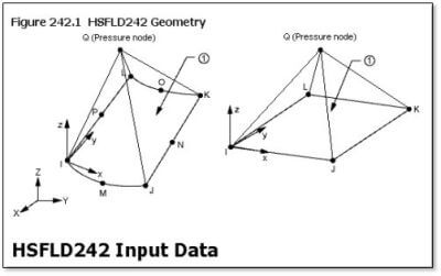
Users should familiarize themselves with the “HSFLD242 3-D Hydrostatic Fluid” and the “HSFLD241 – 2-D Hydrostatic Fluid” elements before proceeding. Their Ansys use is described in the v14.0 Structural Analysis Guide, Chapter 18:
// Structural Analysis Guide // 18. Modeling Hydrostatic Fluids
“Hydrostatic fluid elements are used to model fluids that are fully enclosed by solids (containers). The available elements are:
HSFLD241 for 2-D models (plane stress, axisymmetric, or plane strain)
HSFLD242 for 3-D models
“These elements are formulated for linear and nonlinear static and transient dynamic applications. For more information, see HSFLD241 – 2-D Hydrostatic Fluid and HSFLD242 – 3-D Hydrostatic Fluid in the Mechanical APDL Theory Reference.
“The following topics related to using hydrostatic fluid elements are available:
Hydrostatic Fluid Element Features
Defining Hydrostatic Fluid Elements
Material Definitions and Loading
Example Model Using Hydrostatic Fluid Elements
Results Output”
Description of the HSFLD242 element also comments “This element can be used in linear and nonlinear static and transient analyses and modal analyses.” In more complex applications, these hydrostatic fluid elements can interact with FLUID116 elements in order to capture simplified movement of fluid from one “container” to another. Quoting the Elements Manual description of FLUID116:
// Element Reference // I. Element Library // FLUID116:
“FLUID116 elements can be used to model fluid flow between hydrostatic fluid elements, (HSFLD241 or HSFLD242). A single FLUID116 element connecting the pressure nodes of two different hydrostatic fluid elements is sufficient to model the flow. However, more FLUID116 elements can be added if the actual geometry of the connection needs to be modeled. For FLUID116 elements that are directly or indirectly connected to hydrostatic fluid element, you must set KEYOPT(1) = 3 to convert the fluid element mass flow rate to volume change (for compatibility with the hydrostatic fluid elements).”
For further self-study, the Technology Demonstration Guide has a somewhat complex example of using the HSFLD242 element in a model with fluid compressibility, shell elements, transient behavior, and other details:
// Technology Demonstration Guide // 26. Hydrostatic Fluid Analysis of an Inflating and Rolling Tire
“This example problem demonstrates how to model a fluid that is fully enclosed by a solid (the container). The problem shows how loading on the container and container deformation affect the pressure, volume, density and mass of the contained fluid.”
Setting KEYOPT Values with ET Commands to Employ Fluid Elements | Ansys Workbench
To employ these fluid elements, users will need to create the element types for the Ansys model with the ET command, set KEYOPT values to choose desired options (such as incompressibility), set relevant material properties with MP and TB commands, and enter a Real Constant with the R command if a reference pressure for compressible gas is to be included. Once the TYPE, REAL and MAT values are set for creating the fluid elements, a “pressure node” needs to be created. With the pressure node plus nodes on the surfaces that touch the fluid selected, the ESURF command can “paint” the fluid elements on the interior surface of the model that contains the fluid. The extra node XNODE argument of the ESURF command is used to indicate the “pressure node” number. An initial condition pressure can be applied to the “pressure node” with the IC command and the HDSP label. Stated pressure can be applied with the constraint command D and the HDSP label, during static or transient analysis:
“For hydrostatic fluid elements (HSFLD241 and HSFLD242), the HDSP degree-of-freedom constraint at the pressure node prescribes the pressure value for all the fluid elements sharing the pressure node.”
Simpler uses of these hydrostatic fluid elements will set KEYOPT(1) to “UX, UY, and UZ degrees of freedom at surface nodes, HDSP degree of freedom at pressure node”, KEYOPT(5) to “Fluid mass calculated based on the volume of the fluid element” if mass is wanted (applied to surface may be preferred), and KEYOPT(6) to “Incompressible” if appropriate for liquids. The MP command will set DENS for density, while the TB command is not needed if the fluid is incompressible. The Real constant is only used for reference pressure; not needed if compressible gasses are not of interest. Users can pursue more complex studies with other element settings, including interaction with FLUID116 elements.
See the Elements Manual for detailed information on the HSFLD241 and HSFLD242 elements. Note the comment:
“All hydrostatic fluid elements sharing a pressure node must use the same material property definition and must have the same real constant values (PREF).”
Connection to a face of either a low-order (corner nodes only) or a high-order (mid-side nodes) structural element is supported, as is connection to degenerate forms (triangles) of the faces of the structural elements.
These elements can be further studied in // Verification Manual :: 0 // I. Verification Test Case Descriptions // VM209, and in //Structural Analysis Guide // 18. Modeling Hydrostatic Fluids // 18.4. Example Model Using Hydrostatic Fluid Elements in the v14.0 Help system, both of which use HSFLD241.
Workbench Mechanical Setup
If HSFLD241 or HSFLD242 elements are to be employed in Workbench Mechanical, a user can introduce them with an APDL Commands Object in the Environment branch, with the inner surfaces that touch the fluid identified by a Named Selection. Details are illustrated in the following example.
- For an FEM (Finite Element Model) refresh.
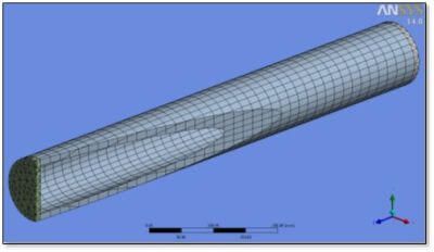
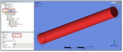
A solid model example was created of a pipe with end caps. For convenience, the central portion and two ends are a multibody part in DesignModeler, so the continuous mesh needs no contact elements. The clearly defined continuous interior surfaces make applying HSFLD242 fluid elements simpler. The following image shows the resulting solid mesh, with a cutaway view created with a section plane so that the interior can be partially seen:
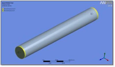
For testing, a simply supported pipe is modeled by placing Remote Displacement supports at the outer perimeters of the end caps of the two cylinder ends. One prevents UX, UY and UZ, while the other prevents UX and UY.
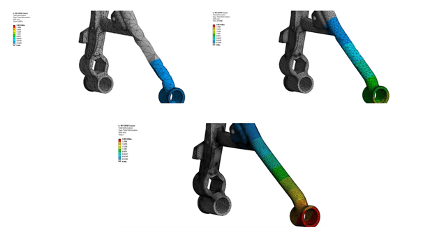
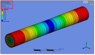
After solving a modal analysis, vibration Mode 3 is transverse. Without added fluid mass, 401 Hz results:
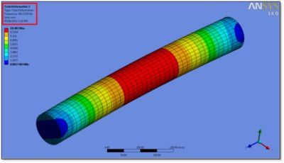
With the added mass of a contained fluid, the frequency of the third mode of vibration drops to 373 Hz:

To introduce the contained fluid into the model, an APDL commands object is employed. A Named Selection is required to define the continuous inner surfaces that will be coated with HSFLD242 elements:
The following Commands Object introduces HSFLD272 elements into the interior of the model:
! Be careful with UNITS because of the material propertites. <<<==========
! It is assumed that NO SYMMETRY effects are in this model.
!
fini
/prep7
*get,typemax,ETYP,,NUM,MAX ! max defined element type
*get,realmax,RCON,,NUM,MAX ! max defined real constant
*get,mat_max,MAT,,NUM,MAX ! max defined material
*get,nodemax,NODE,,NUM,MAX ! highest numbered node in model
! Create a new higher number for element type, real, and material
newnode=nodemax+1000 ! number for pressure node for HSFLD242
newnumber=typemax+1
*if,realmax,ge,newnumber,then
newnumber=realmax+1
*endif
*if,mat_max,ge,newnumber,then
newnumber=mat_max+1
*endif
et,newnumber,HSFLD242 ! 3-D Hydrostatic Fluid Element
keyopt,newnumber,1,0 ! UX, UY, UZ, plus HDSP at pressure node
keyopt,newnumber,5,1 ! Fluid mass calculated based on the volume of the fluid element
keyopt,newnumber,6,1 ! Incompressible
mp,dens,newnumber,1.0e-9 ! Density of Water, kg/mm^3/1000
! Ignoring thermal expansion in this example
! Ignoring TB,FLUID in this example
r,newnumber ! Ignoring Reference pressure for compressible gas
type,newnumber
mat,newnumber
real,newnumber
!
cmsel,s,Inside_Faces ! Select nodes on interior
esln ! Select elements that touch these nodes
n,newnode,0,0,400 ! Pressure node at 0,0,400 (automatically moved to centroid?)
ESURF,newnode ! ESURF HSFLD242 elements over solid element faces
! Extra node “newnode” with ESURF with HSFLD242
allsel
fini
/solu ! return to solving
In the above commands object, no pressure has been applied to the “pressure node” of the HSFD242 elements. This node is number “newnode” as seen in the above APDL code. It has been located at coordinates “0, 0, 400” which is at the centroid of the pipe. This location has been intentionally chosen so that the all HSFLD242 elements have a positive volume. The coordinates can be seen in the details of the body that forms the central region of the pipe:
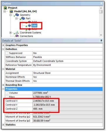
Ansys documentation mentions that the “pressure node” re-locates to the centroid, but that may be only for nonlinear analysis—users should themselves locate it at the centroid. Note the warning about units in the APDL Commands Object. This example model will be solved in millimeters, hence the density of water is being entered as:
mp,dens,newnumber,1.0e-9 ! Density of Water, kg/mm^3/1000
For this example, compressibility of water has been ignored:
et,newnumber,HSFLD242 ! 3-D Hydrostatic Fluid Element
keyopt,newnumber,1,0 ! UX, UY, UZ, plus HDSP at pressure node
keyopt,newnumber,5,1 ! Fluid mass calculated based on the volume of the fluid element
keyopt,newnumber,6,1 ! Incompressible
In the modal analysis, no HDSP pressure has been applied to the “pressure node” with the D constraint command. Testing suggests that applying a pressure constraint in the modal analysis implies that modal vibrations do not change the fluid pressure, affecting modes that deform or accelerate the model in such a manner that there would be pressure variation, so holding the pressure constant changes the frequency inappropriately for some modes.
Once the ESURF command introduces the HSFLD242 elements, the model is ready to solve.
Modes of vibration include rotations about a longitudinal axis in this example. These motions “drag” fluid along with the pipe rotations, requiring fluid shear, artificially reducing the predicted modal vibration frequency. This is a consequence of the HSFLD242 elements sharing the nodes on the inside surface of the solid model. Users need to be aware that such shearing motions may report artificially low frequencies. In the example below, torsional Mode 7 reports a frequency of 1774 Hz with HSFLD242 fluid included. The same mode without fluid reports 1921 Hz. It can be important for users to perform a modal analysis for cases with and without fluids to consider whether a vibration mode really accelerates contained fluid and to observe the consequence for predicted natural frequencies. Note that plots of this twisting motion can make the diameter seem to expand—node movements in modal analysis are virtual displacements, and the diameter does not really increase.
A postprocessing APDL Commands Object can select and plot HSFLD242 elements. It can review pressure at the “pressure node” per the vibration mode (the magnitude is not real physical pressure). Some modes predict a near zero pressure, while others yield a more substantial value. Example commands for pressure review are:
set,first ! Mode 1
prnsol,hdsp
*get,my_hdsp_1,node,newnode,hdsp ! Relative pressure magnitude only in Modal Analysis
set,next ! Mode 2
prnsol,hdsp
*get,my_hdsp_2,node,newnode,hdsp
set,next ! Mode 3
prnsol,hdsp
*get,my_hdsp_3,node,newnode,hdsp
allsel
set,first
Brief testing suggests that positioning of the “pressure node” affects those modes that report a significant pressure in the above measurements, hence its manual placement at the centroid of the straight pipe in this example.
Conclusions | Modeling of a Contained Hydrostatic Fluid Element
HSFLD242 elements in a 3D structure adding contained fluid mass to a model have been illustrated in the Ansys Workbench Mechanical environment. This is an alternative to methods such as coatings of surface effect elements for added mass, or introducing a Point Mass associated with surfaces and set to Deformable. The HSFLD242 element approach can be more accurate in some circumstances, such as higher modes of vibration.
In a structural model, pressure in a contained fluid may vary as the container is strained by various external loads. The HSFLD241 and HSFLD242 element approach can capture this effect, treating the fluid as either incompressible or compressible, according to user choices and inputs. Note the comment in the Elements Manual, “You can define the initial state of the hydrostatic fluid by defining initial pressure (input via the IC command with Lab = HDSP) at the pressure node.” Use of the D command to apply pressure, rather than the IC command, holds it at a stated value that does not automatically change as a container flexes. In a modal analysis, deformations that cause pressure variations affect some modes when a fluid is incompressible or nearly incompressible.
Using Multiple Load Steps to Apply Internal Pressure
In static models, users may wish to use multiple load steps to apply the internal pressure of HSFLD241 or HSFLD242 elements at the appropriate time, and to ramp loads if appropriate for accuracy and convergence. The IC or D command that applies the pressure with Lab = HDSP can be executed at a chosen load step by having an APDL commands object that contains that one command execute only at that load step (set in Details).
The present example has considered modal analysis only. If the modal analysis model was to be prestressed by external loads and/or internal pressure. An upstream static analysis could be run, possibly introducing the internal pressure by using the D command to set an HDSP degree of freedom value at the “pressure node” of the HSFLD242 elements. Alternatively, by using an IC command if the pressure is not constant once the structure deforms. Please note, this is done within an APDL Commands Object in the static analysis environment, and so should not automatically propagate to the modal analysis in Workbench. This is also true for HSFLD241 elements.
Alternative Pressurization Methods in Ansys Workbench
If variation of liquid pressure with depth is to be considered in an upstream analysis, users may prefer to use alternative pressurization methods, or to augment the HSFLD241 and HSFLD242 pressures with a spatially varying pressure. The modal analysis would not use the HDSP pressure on the “pressure node” with a D constraint command if modal vibrations are to capture the effect of those modes that cause pressure variation in the contained fluid.
A variety of simplifications have been employed in the present example. The fluid has been stated to be incompressible with KEYOPT(6). HSFLD242 elements have been attached to the nodes of the inner surface of the solid model, which causes them to be affected by shear-like surface movements in modal analysis, reducing some predicted frequencies in a possibly non-physical manner.
Consideration of Fluid Movements between Connected Interior Volumes
This model does not explore other uses of the HSFLD242 elements, such as interaction with FLUID116 elements in models that solve for the pressure value, and that consider fluid movements between connected interior volumes. No symmetry boundaries have been considered in this model, simplifying the treatment of the HSFLD242 elements and the pressure node.
Users must be careful to employ APDL Commands Object units and solver units appropriately, so that the mass of the added fluid is captured properly.
Users should make efforts to validate the resulting models (such as HSFLD241). The present example is “use at your own risk” and as usual, users should read the Ansys Help system materials carefully, and validate any steps taken to employ these analysis techniques. Users should create small simple models with known solutions to learn new analysis techniques, prior to employing them in complex industrial-sized models.
Contact for Additional Ansys Mechanical and/or Modeling Contained Fluid Elements
Finally, we hope that you can make productive use of the Contained Fluid in FEA Modeling support article, and varying supportive commands/assignments for your Ansys Mechanical models. For more information, or to request engineering expertise for a particular use-case scenario surrounding FEA Modeling, APDL commands or Node Assignments, or general Fluids applications, please contact us here.