fbpx

Best Practice Concerning Strain Gage Length | Strain-Sensitive Grid Length

When possible, the gage length should be no more than 0.1 times the radius of a hole, fillet, or notch, or the corresponding dimension of any other stress raiser where the strain measurement is to be made, as a rule of thumb.


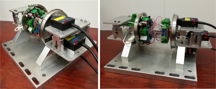
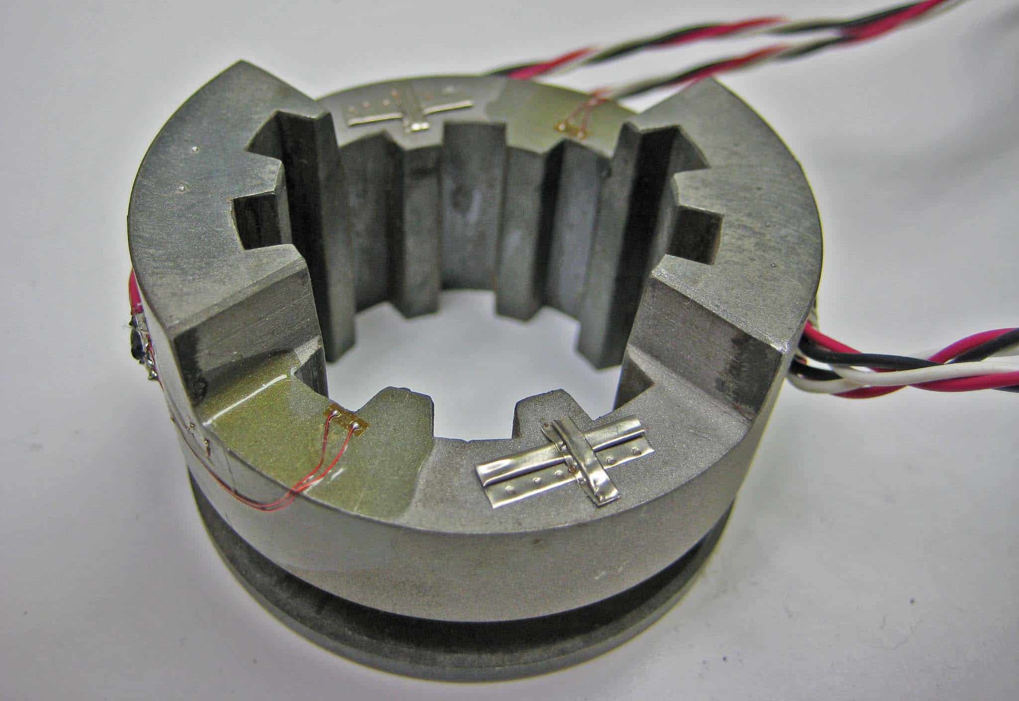
Consider the Strain Gage Length Relative to Radius of a Hole

When possible, the gage length should be no more than 0.1 times the radius of a hole, fillet, or notch, or the corresponding dimension of any other stress raiser where the strain measurement is to be made, as a rule of thumb.

This rule of thumb can lead to very short gage lengths in stress-raiser designs with major dimensions less than, say, 0.5 in (13 mm). Because the use of a small strain gage might generate a slew of other issues, compromise is frequently required.

Strain gages with a gage length of less than 0.125 in (3 mm) have a poor performance.  This condition is particularly noticeable in terms of maximum allowed elongation, static strain stability, and alternating cycle strain endurance. A larger gage may be necessary if any of these factors exceed the inaccuracy caused by strain averaging.

Advantages of Longer Gages during Strain Analysis

Larger gages provide a number of advantages that are worth noting when they can be used. In practically every part of the installation and wiring operation, they are frequently easier to handle than micro gages (in gage lengths up to, say, 0.5 in or 13 mm).

Furthermore, large gages promote heat dissipation by introducing lower wattage per unit of grid surface for the same nominal gage resistance. When the gage is put on a plastic or other substrate with weak heat transfer qualities, this issue is critical.

High temperatures in the grid, backing, adhesive, and test specimen surface are caused by insufficient heat dissipation, which can compromise gage performance and accuracy.

Strain Gauge Measurement on Disparate Materials

Strain measurement on diverse materials is yet another application of big strain gages – in this instance, often very large gages. Take, for example, concrete, which is made up of aggregate (typically stone) and cement.

When measuring stresses in a concrete structure, it’s usually best to use a strain gage with enough gage length to span multiple pieces of aggregate and measure the structure’s representative strain.

In other words, in such cases, the average strain is normally sought rather than the substantial local variations in strain that occur at the interfaces of aggregate particles and cement.

Catering Strain Gauge Length to Materials Uniqueness

When measuring strains on buildings constructed of composite materials of any kind, the gage length should be substantial in comparison to the dimensions of the material’s uniqueness.

When the above factors do not demand differently, gage lengths in the range of 0.125 to 0.25 in (3 to 6 mm) are preferable. In this range of lengths, you’ll find the widest number of gage patterns and stock gages.

Furthermore, larger or expanded sizes typically cost more, and larger gages do not significantly increase fatigue life, stability, or elongation, whereas shorter gages are typically poorer in these areas.

Practical Application of Standard Strain-Sensitive Grids

Strain gages are ideal for verifying stress and displacement simulation models.  The strain measurements are taken at specific locations and correlated with the simulation results.

Modeling assumptions such as boundary conditions, contacts, and loads may be updated to make the simulation better fit the observed behavior.

Strain-Gauge-Testing-Rail-Dog-Slim-SimuTech-Group


Once the model accurately reflects the measurements, more detailed information about the system can be inferred.

In addition, simulations of the modified system can be used to predict behavior with confidence.

SimuTech Group specializes in both strain gage measurement as well as simulation, allowing seamless support when conducting investigations.

Contact for Strain-Sensitive Grid Testing


Related Mechanical Testing Services Offered


Turbine Blade Frequency

For new, refurbished, or reverse engineered turbine blades (buckets) to ensure that natural frequencies are within specifications.

Torsional Vibration

Determine the natural frequencies and mode shapes of a rotor train as it twists about the axis of rotation.

Vibration Diagnostics

Identify the root cause of noise and vibration problems in machinery via ODS, spectral, order tracking or joint time frequency analysis.