New Feature Preserves Geometry Associativity in Ansys Mechanical Release 2023R1
In many industries, including aerospace, defense, automotive, power generation, oil and gas, and power electronics, simulation software Ansys Mechanical is reputed for its ability to work with CAD geometry through meshing, contacts, constraints, solving, parameterization, and optimization.
Product design engineers running simulations will typically conduct multiple analyses with design changes on the underlying geometry until a final optimal design satisfying the structural or thermal objectives is achieved. When editing the geometry, associativity in Mechanical to materials, contacts, mesh settings, and constraints can potentially be completely lost or become underdefined. In such cases, the engineer will typically see multiple question marks in the Mechanical outline tree because of lost associativity. The engineer then will have to go through each of the associativity changes and fix them manually in order to complete and re-run the simulation. This could lead to longer model building time, especially in complex assemblies. Geometry Associativity in 2023 R1 Mechanical alleviates this problem by automatically detecting and re-establishing scoping.
New Geometry Associativity Feature Alleviates Manual Scoping
This new geometry associativity feature introduces a scoping wizard tool. The scoping wizard tool automatically detects all geometry changes that become lost during an update and reestablish scoping. This feature is on by default. It also has an ‘Automatic Scoping Update’ preference which allows the application to automatically correct geometry-based scoping that becomes lost following a geometry update.
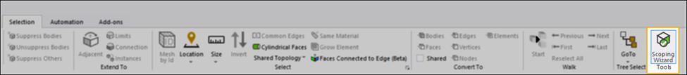
Figure 1. Geometry Associativity Scoping Wizard
How Does the Geometry Associativity Feature Work?
When an updated geometry model is refreshed in Mechanical, various parts of the geometry are color coded depending on the associativity. The engineer can then work their way through the list to visualize which pieces have been reassociated and what has not been scoped automatically. Items which Mechanical locates and can be automatically reassociated are colored green, items with multiple matches are colored yellow and items which are unable to be automatically reassociated are colored red. Furthermore, the worksheet uses the color scheme to indicate if one or more of the conditions exist, such as the Named Selection, ‘AllFaces’, in the example shown below that displays all three colors.
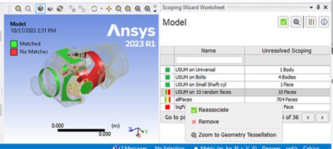
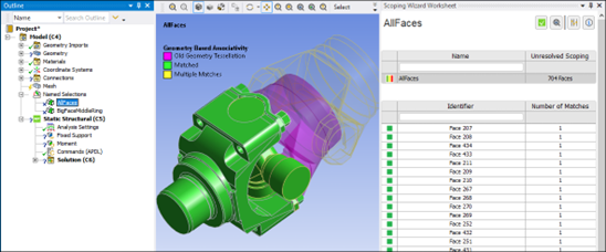
Figure 2. Efficiently reestablish associativity after editing a CAD model using the new Scoping Wizard.
Once the scoping wizard is selected all objects with unresolved scoping are listed in the worksheet pane as well as the model tree. The feature can also be accessed via the context (right click) based menu. A Fix All Scoping option allows the engineer to automatically correct all recovered scoping.
The Scoping Wizard pane enables the engineer to:
- Change display settings, fix scoping, show an information pane, and zoom on a scoping.
- View a list of unresolved objects.
- Filter the list based on object name or number of unresolved scoping.
- Navigate through long lists of unresolved objects.
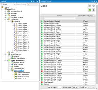
Figure 3. Connection objects with unresolved scoping
If an engineer double-clicks a table row, or selects an unresolved object in the tree, the pane shows information specific to the object and its (unresolved) scoping. The following example shows a Contact Region that has lost scoping. The panel displays the object type/name (Contact Region), the number of unresolved geometric entities, whether the application identified a scoping match, and the original application-assigned ID for the entities. The first item in the worksheet is selected by default, and the parts are highlighted in the geometry window.
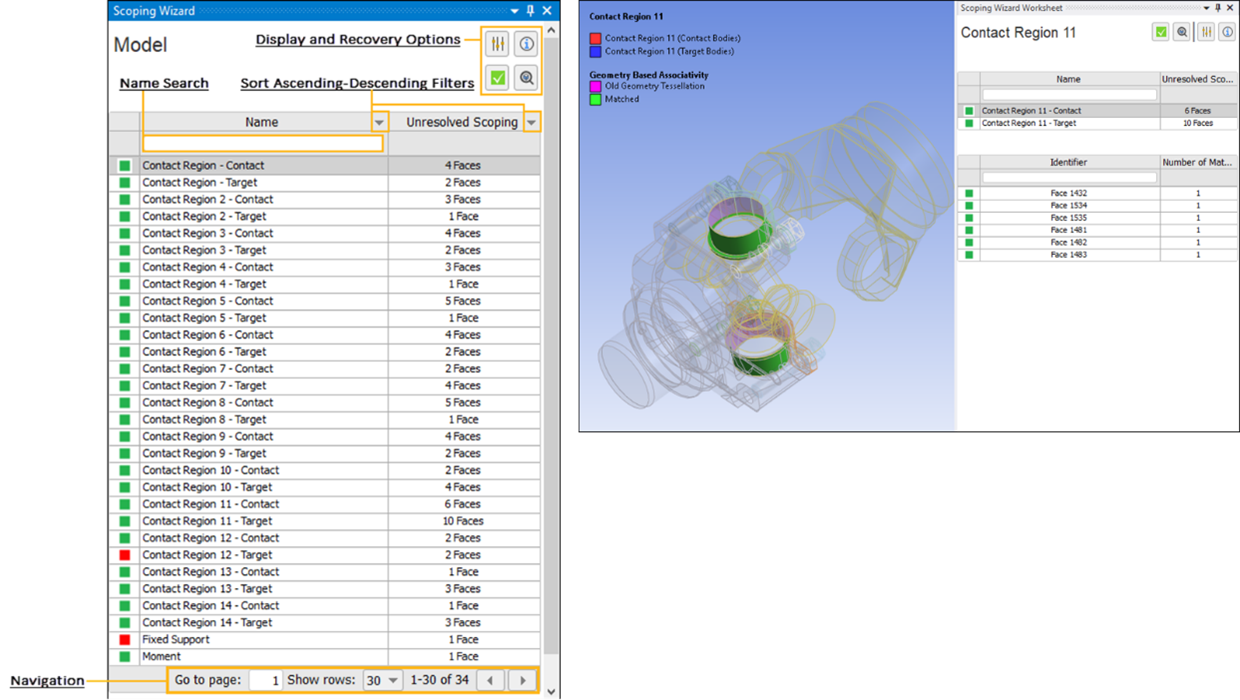
Figure 4. Example of a contact region with lost scoping
As with any new feature, Geometry Associativity does have limitations which may be addressed in future releases. The feature does not yet recover mesh-based (node, element-face, element) scoping.
The geometry associativity feature automatically detects geometry scoping that becomes lost during geometry or design updates and offers users a tool for automatically re-establishing and fixing most detectable changes. This reduces model building time with design/geometry changes especially with large, complex models. Engineers spend less time manually re-scoping after design changes and more time optimizing their designs, leading to accelerated time to market and more robust product designs.