Ansys Clock FX allows you to calculate clock jitter with variation on a full SoC, and control the effects of supply noise variation.
Clock FX’s unique cell modeling delivers SPICE accuracy timing for any voltage or variation condition with a single library. Clock FX has a fully threaded and distributed architecture, with the ability to scale to thousands of CPUs.

✔ Clock Mesh Handling
✔ DvD Sign-off Flow
✔ Native DvD Handoff
✔ Clock Mesh Handling
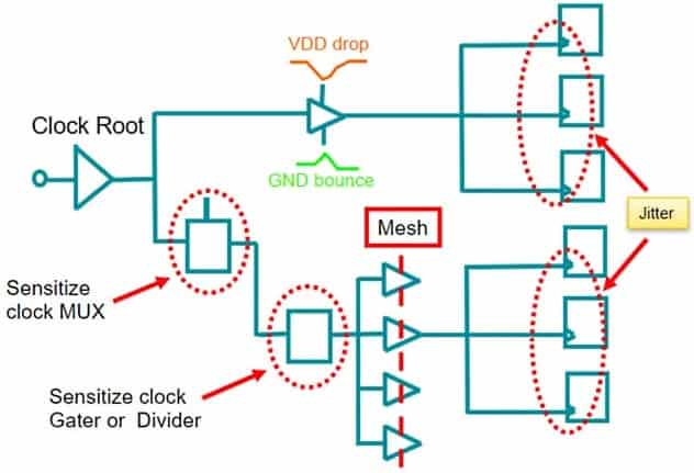
✔ Clock Jitter Analysis
✔ Simulate Entire Clock

Clock FX (SoC Software) mines the dynamic voltage drop on the clock network produced by RedHawk-SC to calculate clock jitter with SPICE-level accuracy. In addition, the software also accounts for accurate multi-voltage analysis and simulates the delay impact of supply variation on the clock paths.


Clock FX (SoC Software) leverages the SPICE transistor models and full waveform propagation to provide the accuracy needed to get reliable results at ultra-low voltage for advanced processes. Miller-capacitance and other effects are handled correctly, with no shortcuts.
Core database including (but not limited to):
Power supplies
Input components
Passive components
Discrete semiconductors
Logic gates
Integrated circuits (ICs)
Output components