Axial Flux Motor
Induction Motor
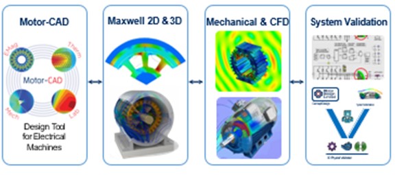
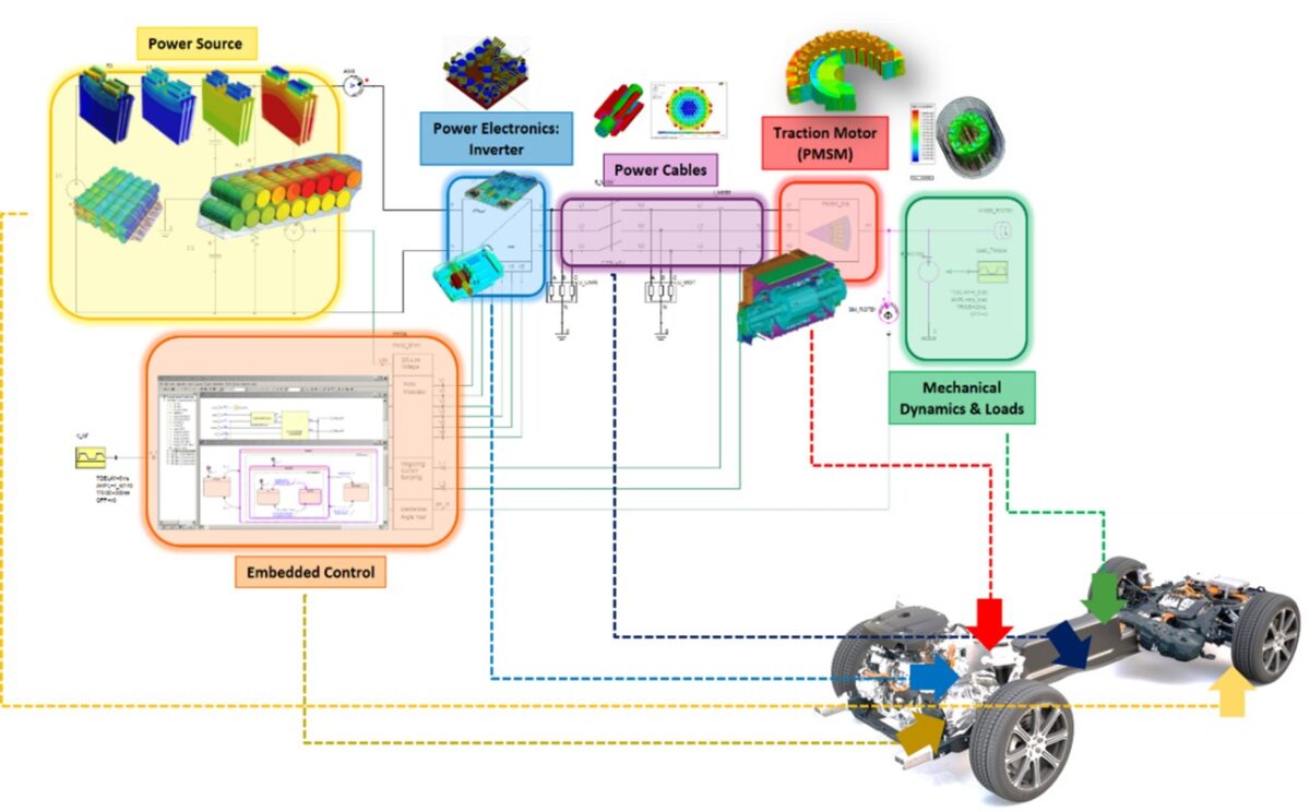
The non-linear material properties, eddy current effect, proximity effect, hysteresis, and demagnetization are all covered. The motor performance of the electric machine can be estimated in a realistic system with complicated driver circuit and customized mechanical loads.
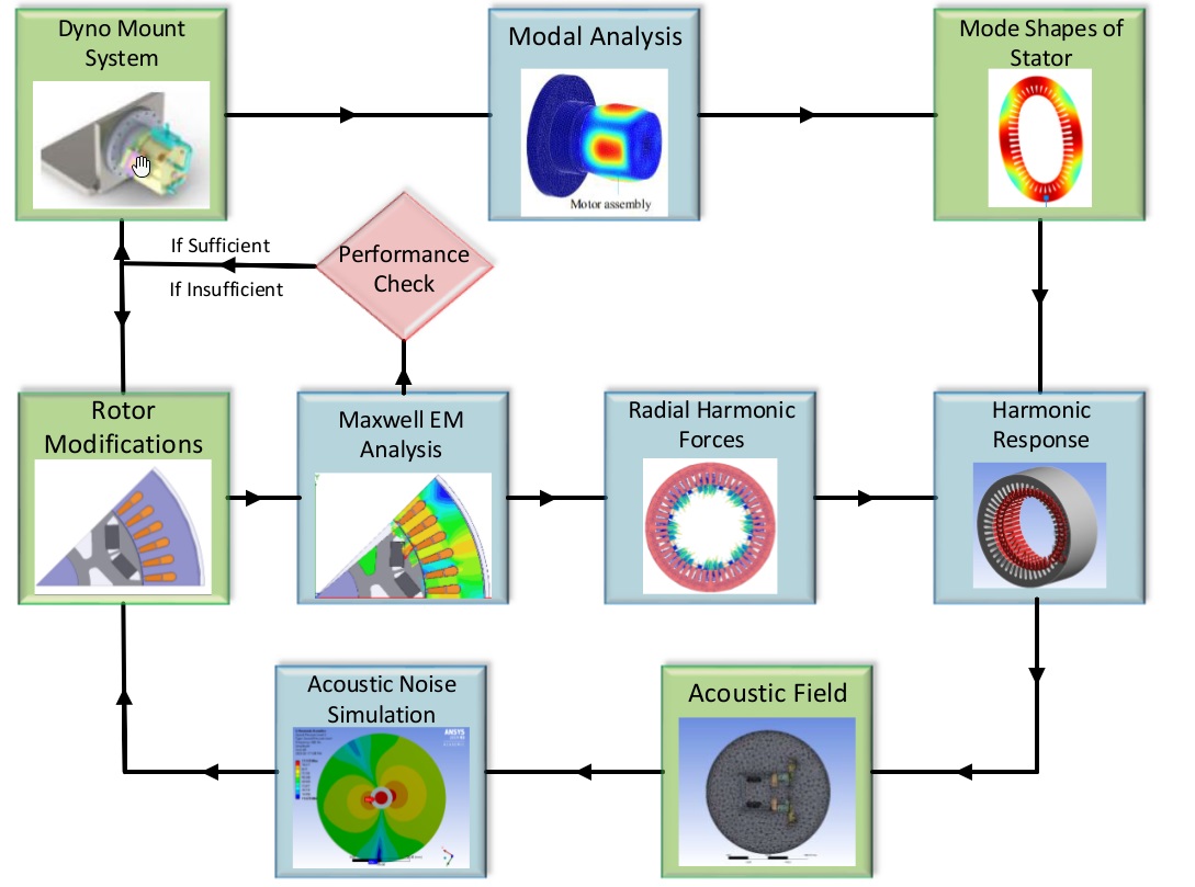
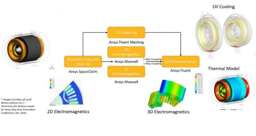
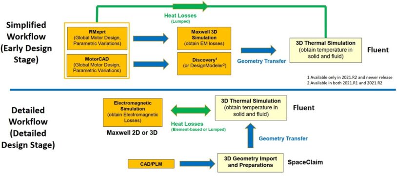
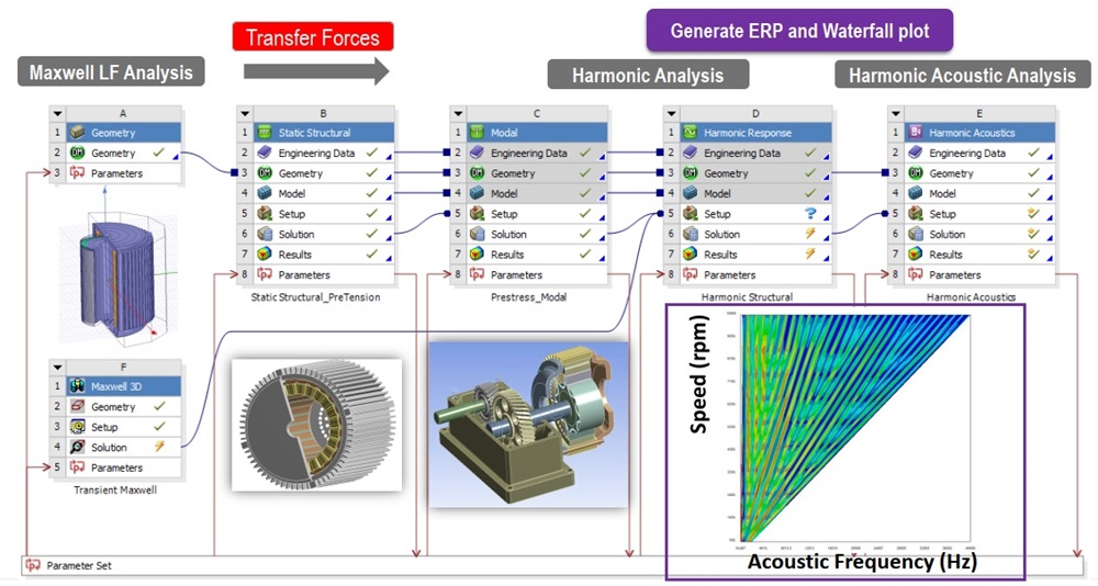
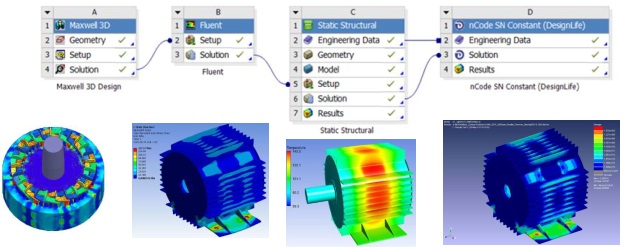
We study the structural vibrations caused by the magnetic loads and the sound produced by these vibrations to simulate noise for NVH applications. For electric machine simulation, thermal models are used for temperature dependent effects on magnets. The motor performance can be extracted into reduced order models to study the effects of detailed controller models.
Magnetic Field Distribution
Core Loss Distribution
Electromagnetic Torque
Electric Machines Efficiency Mapping
Electric Machine Core Loss Distribution
Rotor Magnetic Force Distribution
For engineers tasked with creating and evaluating 3D/2D structures, such as motors, actuators, transformers, and other electric and electromechanical devices, ANSYS Maxwell is a comprehensive electromagnetic field simulation program.
EEE stands for Electrical and Electronics Engineering.
Electrical and electronics are two different fields; one is solely based on electricity, while the other, EEE, combines both. EE Electronic engineering studies small-scale electronic systems, such as computers and integrated circuits, while electrical engineering focuses with issues related to large-scale electrical, power transmission, and motor control.
Electromagnetic design, thermal design, structural design, multi-physics design, material design, and manufacturing process design are a few broad design methodologies that can be used in a variety of disciplines and domains.
Electrical machines have undergone significant advancement throughout the past century. The expansion of design and control’s applications in new domains is made possible by new concepts. They are regarded as crucial parts in a variety of industrial settings, including those involving power systems, industries, power plants, electrical vehicles, and residential appliances.
Electrical machines come in a variety of forms. Some examples include synchronous machines, induction machines, transformers, direct current (DC) machines, and reluctance synchronous machines.
When electricity is generated, transmitted, and used, electrical machines are a part of the energy conversion process. In a power plant, a turbine generator transforms the energy produced by burning coal, natural gas, etc. into electric energy that is sent to customers, such as motors that power machinery in homes, businesses, and transportation systems.
Rotating electrical machines are of relevance to the majority of applications. Given that an electrical machine’s energy direction is reversible, the rotating electrical machine can function without requiring any construction alterations as a motor or generator.
Modern methods for designing electrical machines include:
Any system’s design must take into account factors like prediction accuracy, cost, quality, and turnaround time.
A design basically entails computing the weights, material requirements, output characteristics, and performance in line with predetermined international standards. It also involves calculating the dimensions of various machine elements and components.
Due to the possibility that the computed parameters would not match the final tested performance, the design must be fixed while taking into account the design analysis and prior operating experience of such machines.
The practical approach in the case of larger machines is to create a computer program for the overall design, incorporating the constraints’ parameters, and run the program for many possibilities before choosing the chosen design.
Even while the final design may satisfy all the necessary requirements, it need not be the best one in terms of the active materials’ weight, cost, and certain performance factors like efficiency, temperature rise, etc.
The transformer is the electrical device with the highest efficiency. Transformer efficiency is greater than 95%. The autotransformer operates at a close to 98 percent efficiency.
The lack of moving parts makes transformers superior to ac or dc machines. Losses are thus decreased. Higher efficiency is as a result attained.
Since they must contend with several losses, such as core loss, copper loss, friction, windage loss, etc., which consume a sizeable portion of the machine’s power supplies, AC and DC motors are typically not very efficient.
The majority of electric motors are made to operate between 50% and 100% of their rated load.
The maximum efficiency is typically in the range of 75% of the rated load. Therefore, the allowable load range for a 10-horsepower (hp) motor is between 5 and 10 hp; its peak efficiency is at 7.5 hp. Below roughly 50% load, a motor’s efficiency tends to drop off sharply.
It is feasible to determine motor loads by measuring actual motor speed with a tachometer. A battery-powered stroboscopic tachometer is the safest, most practical, and frequently most accurate type of tachometer.
Avoid using mechanical tachometers, plug-in tachometers, and tachometers that demand that the motor be stopped in order to apply paint or reflective tape.
If the engineer is familiar with the technique, slip measurements can be used to determine the motor load.
Due to its ease of use and safety benefits, the speed/slip method of measuring motor part-load is frequently preferred. The majority of motors are designed so that a tachometer or strobe light can see the shaft.
The slip method’s accuracy, however, is not very good. The biggest question mark is the manufacturer-reported nameplate full-load speed tolerance of 20% that NEMA permits.
Manufacturers typically round their claimed full-load speed values to a multiple of 5 rpm due to this wide tolerance.
The slip method depends on the discrepancy between full-load nameplate and synchronous speeds, which may seem minor given that 5 rpm is a tiny percentage of the full-load speed. A seemingly insignificant 5 rpm discrepancy results in a 12 percent variation in the computed load when there is a 40 rpm “correct” slip.
Slip also fluctuates inversely with respect to the square of the voltage at the motor terminals, which is subject to a separate NEMA tolerance of 10%. Of course, the slip load equation can be modified to include a voltage adjustment factor.
Transformers, generators, and motors are the three primary categories of electric machines.
Electric machines or electrical machines are any devices that need electrical energy to function. Electricity may be used as the machine’s input, output, or both.
DC Generator: The rotor of a DC generator is called the armature (an assemblage of conductors), and the stator is where the electromagnetic poles are joined. Alternating current is generated in the armature as the rotor rotates within the stator and is collected by commutator segments linked to the motor shaft. Through the commutator, the generated alternating current in the armature is changed to direct current.
AC Generator: The armature of an alternator is fastened to the stator’s interior edge. In the stator, the electromagnet revolves. The external circuit receives a direct feed of the electricity produced by the static armature. Through slip rings, the DC supply powers the rotor electromagnet.
The AC motor comes in two varieties. Synchronous and induction motors.
The buck does not stop here, however. In fact, there are a wide variety of other electric motor types, including servo motors, stepper motors, hystersis motors, and others.