fbpx

Finite Element Method Experts

Markets have become significantly more competitive and having small gains in performance can make or break success.

FEA Optimization

Optimizing your Finite Element Analysis

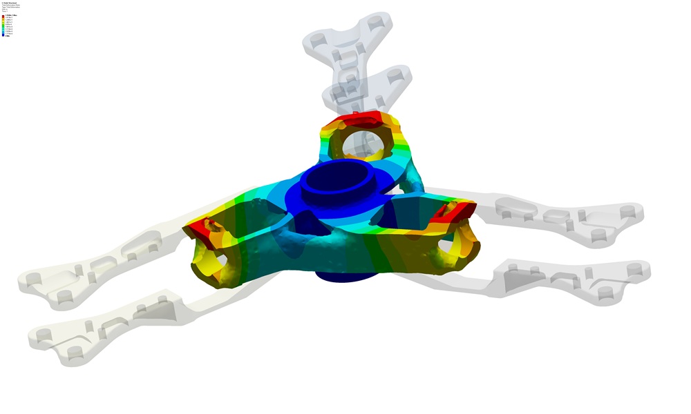
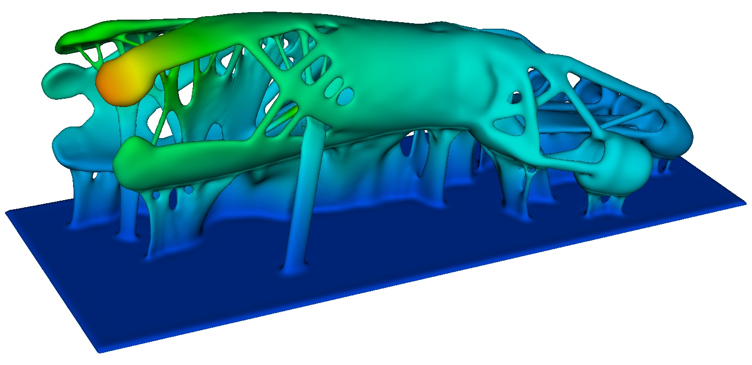
FEA Optimization can be measured in many ways, cost, weight, deflection, pressure drop, and life are but a few. By either parameterization or topological optimization designs can be improved to their maximum potential.

The siblings to optimization are sensitivity and robustness. Some designs may have great performance under ideal manufacturing and environmental conditions, but minor variations quickly degrade this. Often the best design isn’t the one that has the best performance for one condition but has good performance over a variety of conditions.

It should be noted that this can be used to reduce costs as well.  Maintaining tight machine tolerances sensitive to operational or environment changes will increase costs if load variation cannot be managed.  However, if the design is not sensitive to variable conditions; processes can be expanded, and enhanced via FEA optimization.

Additive-manufacturing-FEA-OptimizationAM-simulation-applications-SimuTech-Group-CFD-FEA-Hi-Tech
Finite-Element-Analysis-Consulting-Engineers-Failure-Analysis-Structural-Assessment-FEA-Enhancement

FEA Optimization | Cutting Costs & Enhancing Designs

Products’ and systems’ performance can be significantly enhanced, and costs reduced, thanks to FEA insights.

The substantial resources required for creating and testing physical prototypes are rendered useless. Greater flexibility and cost reductions are possible with FEA, although the procedure can be challenging.

It demands FEA engineers with experience who can use the right tools to gather pertinent data and have the knowledge to interpret the results. FEA engineers will be able to make the proper assumptions and navigate the analysis in a way that addresses all important issues.

Having a skilled team of FEA consultants on staff enables businesses and designers to develop products more effectively and quickly. This aids in solving challenging engineering issues, validating component designs, and assessing performance under various operating conditions.

FEA Application in Failure Analysis

When examining and describing the quantitative and qualitative methodologies used to ascertain the primary reason for an event that results in a failure, FEA is frequently employed.

Due to increased accessibility of commercial software, the application of FEA for mechanical failure has evolved into a necessary tool.  In this sequence, the failure’s historical context is provided to the software, along with additional boundary constraints.

Finite-Element-Analysis-Consulting-Engineers-Failure-Analysis-Structural-Assessment

FEA Mechanical Failure

In a recent finite element analysis consulting study, the stress distribution of a failed 28MW horizontal hydroturbine shaft was examined using FEM.

Records and data cataloging, corresponding to the fractography and metallographic observations, were input for simulation. Both typical and high load (extreme) situations present during startup were considered in the finite element study.

The part was assigned a predicted working life of 210,000 hours, and failure was found after 164,100 hours in use.

The fracture surface revealed a fatigue pattern with clear ratchet marks upon ocular inspection. Further examination of the fracture surface revealed areas of increased porosity and clearly visible distorted fatigue lines surrounding numerous gas holes.

According to an original document (required for any commercial building permit), the shaft underwent heat treatment to finish the austenization process. Metallographic analysis, however, revealed cast ferrite-pearlite with an undissolved dendritic structure, which may have been the result of an incorrect heat treatment procedure. A sizable non-metallic inclusion was also noticed in the cast component via the Finite Element Method (FEM).

FEA-Consulting-Flange-Shaft-SimuTech-Group

Finite Element Method (FEM) Application

Two typical load cases—one obtained from the manufacturer’s manual and the other the static load experienced during startup—were numerically calculated to identify the shaft flange stress states.

The maximum stress was found to be at the location (crack start) at the shaft flange, according to calculations using the finite element method for both load circumstances.

The results of the mechanical and chemical composition tests revealed that the material did not meet the necessary minimum requirement. As a result, stress was more likely to cause the failure at the area of the crack. The failed area had a significant distribution of stress, according to finite element analysis.

The measured tensile stress value on the shaft flange transition radius as a result of the load in case two was higher than required.  This was evidenced by the stress intensity factor at the crack tip being higher than the material threshold, according to the results of the finite element analysis.

The shaft failure was determined to be caused by corrosion fatigue. Inadequate corrosion shielding at the failing location was the primary contributing factor in this occurrence.

A lack of periodic inspection was also denoted as a primary factor in the failure (not to mention, a building code violation), both of which were required given the high level of stress in the area.

Finite-Element-Analysis-Consulting-Engineers-Failure-Analysis-Structural-Assessment-Crack-Graph

Recent FEA Consulting Projects | Optimized Finite Element Analysis

Plastic Deformation

Examining material (plastic) distortion subject to tensile and torsional stresses exceeding yield strength, causing undesired elongation and buckling.

Modal Analysis

Identifying the “problematic” resonance frequencies and eigenmodes of systems without having to be aware of damping or excitation effects.

Harmonic Analysis

Depending on the clients needs and the available input data, determining how much damping should be added to the computation for practical efficacy.

Stress Mitigation, Deflection Under Pressure

Maximization of deflection under pressure load, while minimizing stress.

Structural FEA of Power Plant Frame

Structural FEA optimization of an integral power plant frame.

Optimization under Extreme Loading

Optimization of power generating device under extreme thermal and structural loads.

All FEA Consulting Services | Application & Industries

Dynamic Analysis

Kinematic Analysis

ASME Boiler and Pressure Vessel Code

Composites

Thermal Analysis (Thermal Stress)

Failure Analysis (Durability and Fatigue)

Optimization

Industry and Military Standards