La technologie de maillage couramment Ansys fournit un logiciel de maillage intelligent, automatisé et à usage général, haute performance et automatisé. Les simulations produisent le maillage le plus approprié pour des solutions multiphysiques précises et efficaces.
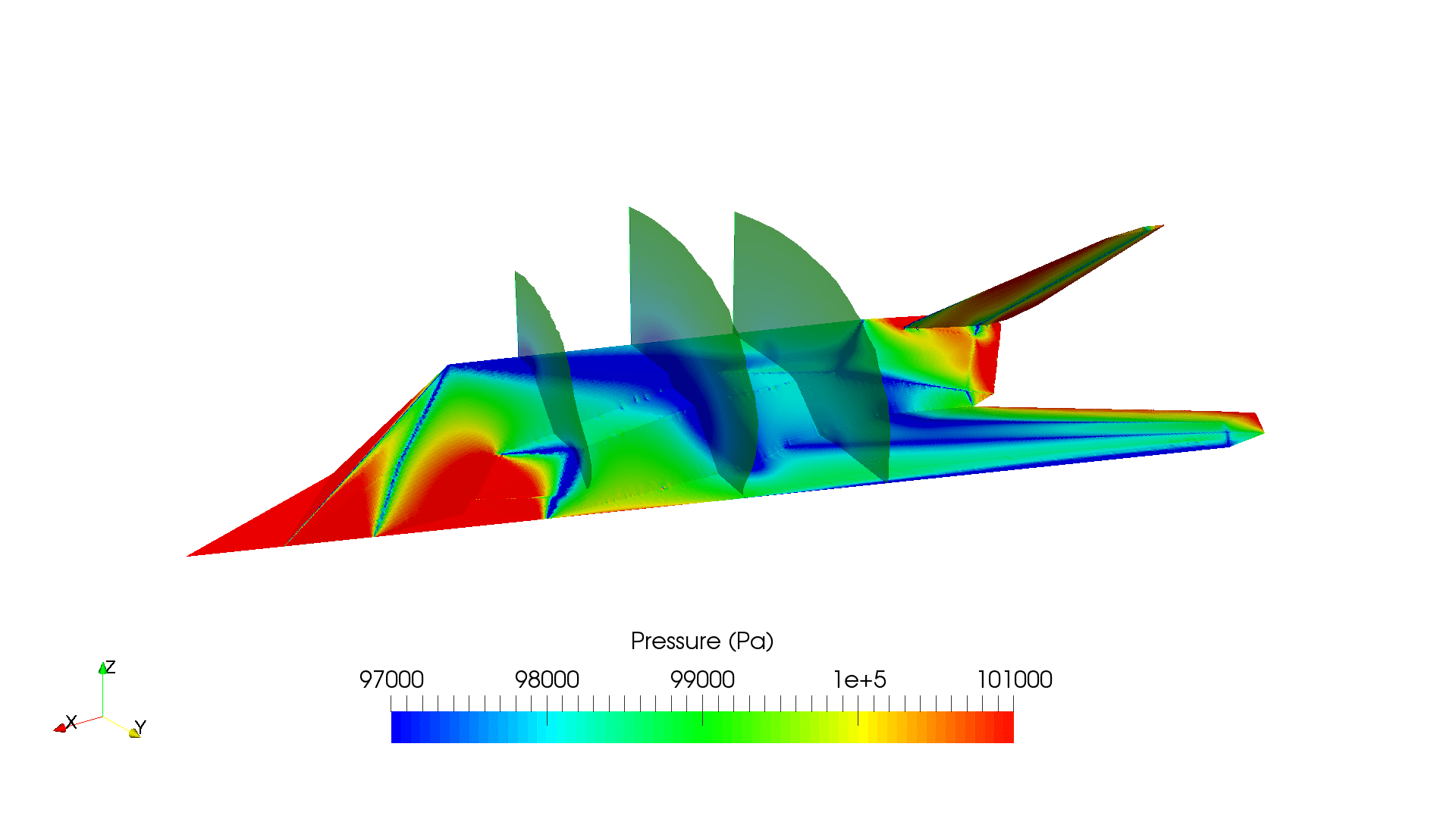
L’application du maillage fluide Ansys va du maillage facile et automatique au maillage hautement conçu, pour des projets de conception à plus grande échelle et / ou plus complexes. Les valeurs par défaut intelligentes sont intégrées dans le logiciel pour faire du maillage une tâche indolore et intuitive, fournissant la résolution nécessaire pour capturer correctement les gradients de solution pour des résultats fiables.

✔ Parallel Processing
✔ Automation and Scripting
✔ Adaption and Refinement
✔ Structured and Unstructured

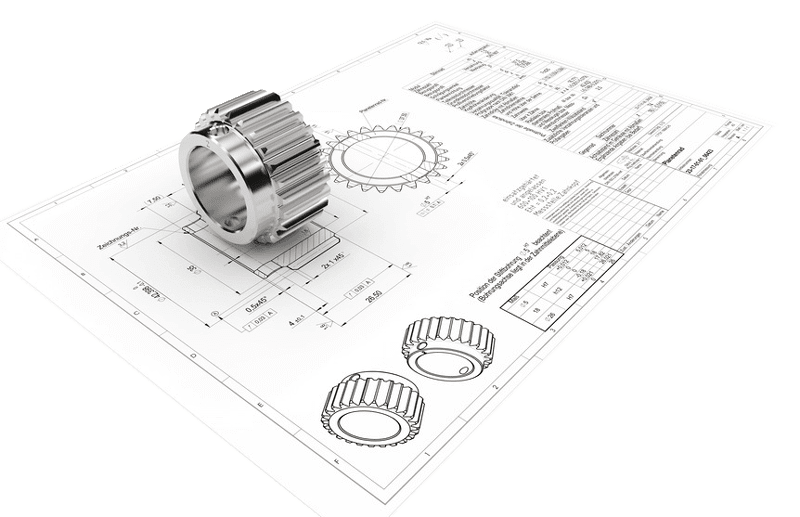
Simulation is a crucial tool for many industries, particularly in those involving structural analysis. In fact, according to Grand View Research, the global simulation software market is expected to grow at a compound annual growth rate (CAGR) of 17.1% from 2021 to 2028. This is a significant increase — chiefly due to the many advantages simulation software provides business, including decreases in product development costs, physical tests, and defective prototypes.
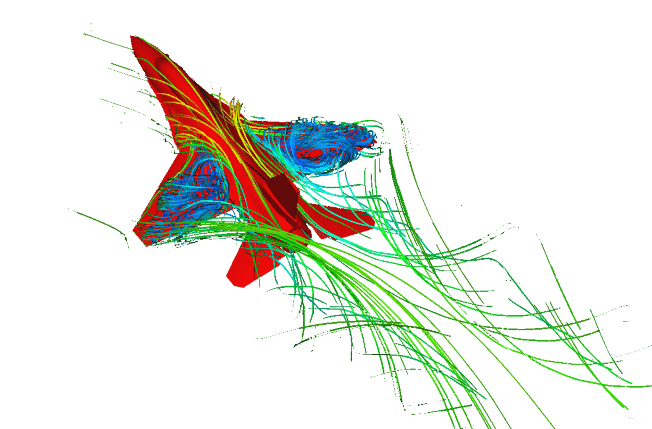
In computer-aided engineering (CAE) functions like simulation, there are categories of software to analyze your merchandise such as finite element analysis (FEA), computational fluid dynamics (CFD) and many others. To conduct a CAE simulation, there are three important steps to an analysis: pre-processing, solving and post-processing. Ansys Meshing incorporates all three of these steps in for an all-encompassing simulation suite.
There are two main types of meshing methods. For these purposes, we are referring to 3D models:
Hex or “brick” elements generally result in more accurate results at lower element counts than tet elements. If it is a complex geometry, tet elements may be the best choice. These default or automatic meshing methods may be enough to get you where you need to go, however, there are additional methods that can give you more mesh control.
In Mechanical, you can use a Multizone method, which is a hybrid of hex and tet elements that allows you to mesh different parts of the geometry with different methods. This allows you to perform less geometry preparation and have more local control meshes.
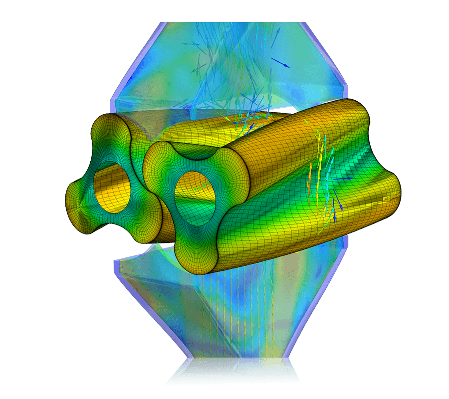
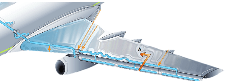
Mesh morphing involves the adaption of a computational grid modified for computer aided engineering (CAE). For example, the solid or shell mesh of a structural component ready to be processed by an FEA solver, or the volume mesh complete with boundary provisions for a CFD solver, can take on a new shape by merely updating nodal positions. This indicates that the topology of the mesh (connectivity, nodes count, cells count, etc.) stays the same. Just the x,y,z coordinates of the nodes in the section of the model undertaking a shape modification are updated during this process.
Mesh morphing can be used for critical purposes:
Another advantage of Mesh Morphing is speed. Typically, mesh morphing is quicker than remeshing for a number of reasons:
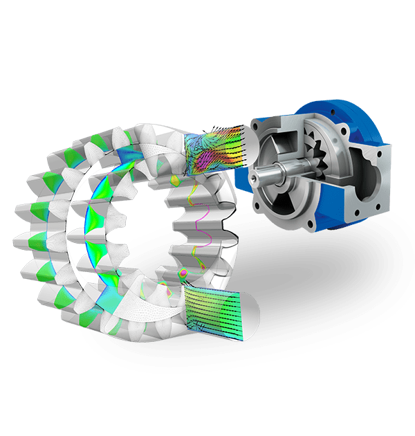
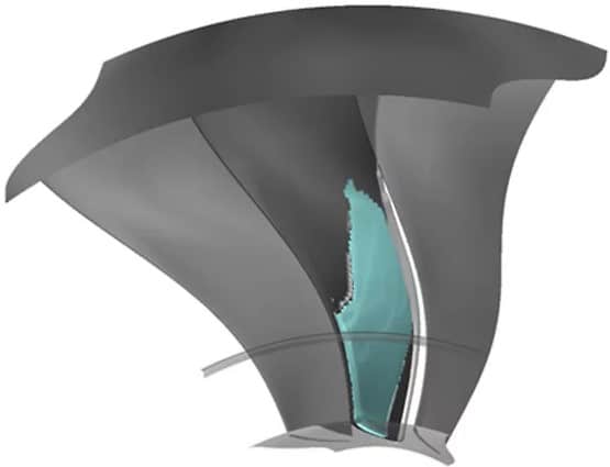
Go from a single passage up to multi-stage machines to obtain excellent aerodynamic performance.
Go from a single passage up to multi-stage machines to obtain excellent aerodynamic performance.