Contact Us
In this blog I provide an overview of using the Motor-CAD Emag module to model the electromagnetics of a motor, including geometry, motor winding configuration, and materials, using an Interior Permanent Magnet (IPM) motor as an example. The various tabs contain many options and settings to configure. Fine tuning these settings allows the user to obtain an accurate motor model and realistic motor performance.
PHYSICS MODEL and MOTOR TYPE GEOMETRY
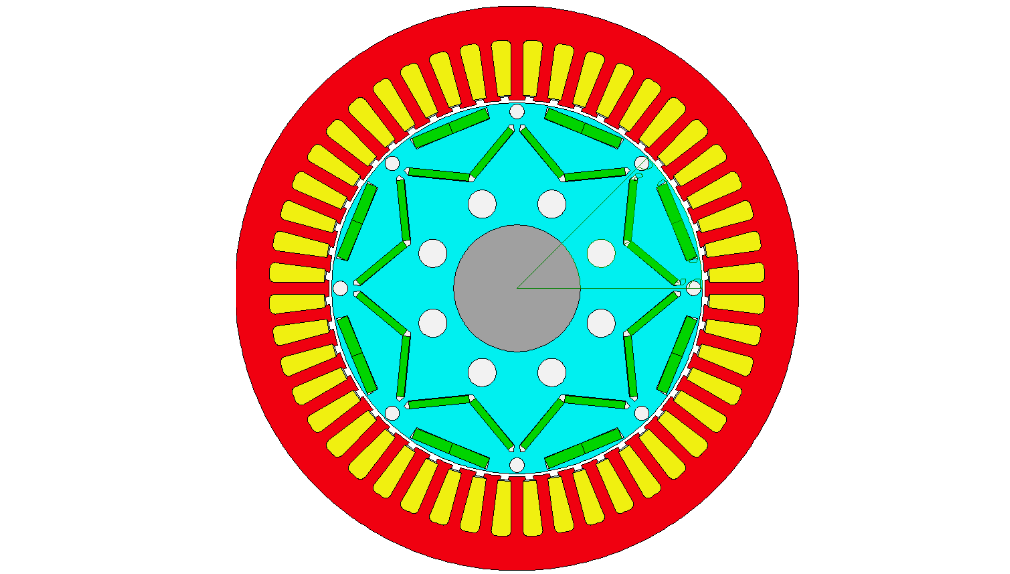
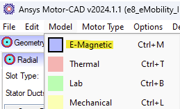
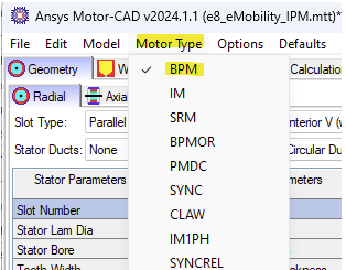
In Motor-CAD we need to choose which physics model and motor model we are going to use. After the selection of the motor model is made a default motor model appears and the menu tabs will appear in the color corresponding to the physics as shown below. In Emag the tabs appear in blue color. In this example we are using E-magnetics (Emag) for the physics model and BPM (Brushless Permanent Magnet) for the motor model.
Physics Model
Motor Model
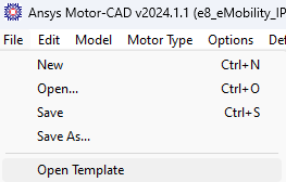
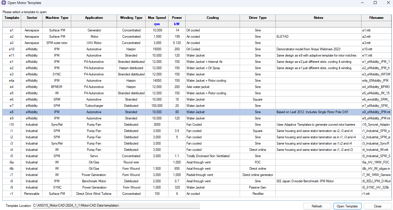
Alternatively, we can develop a motor model starting from using a template by selecting File > Open Template > select a template. In this example we used the e8 template.
GEOMETRY
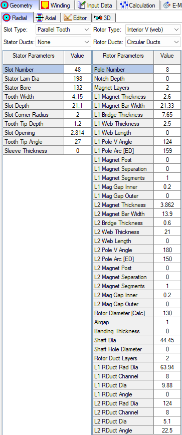
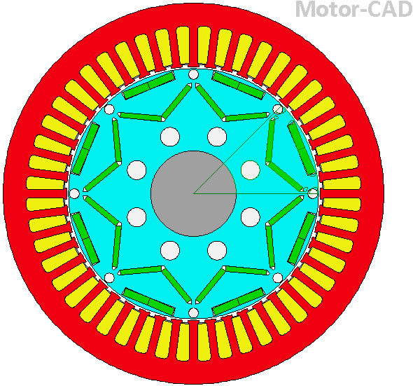
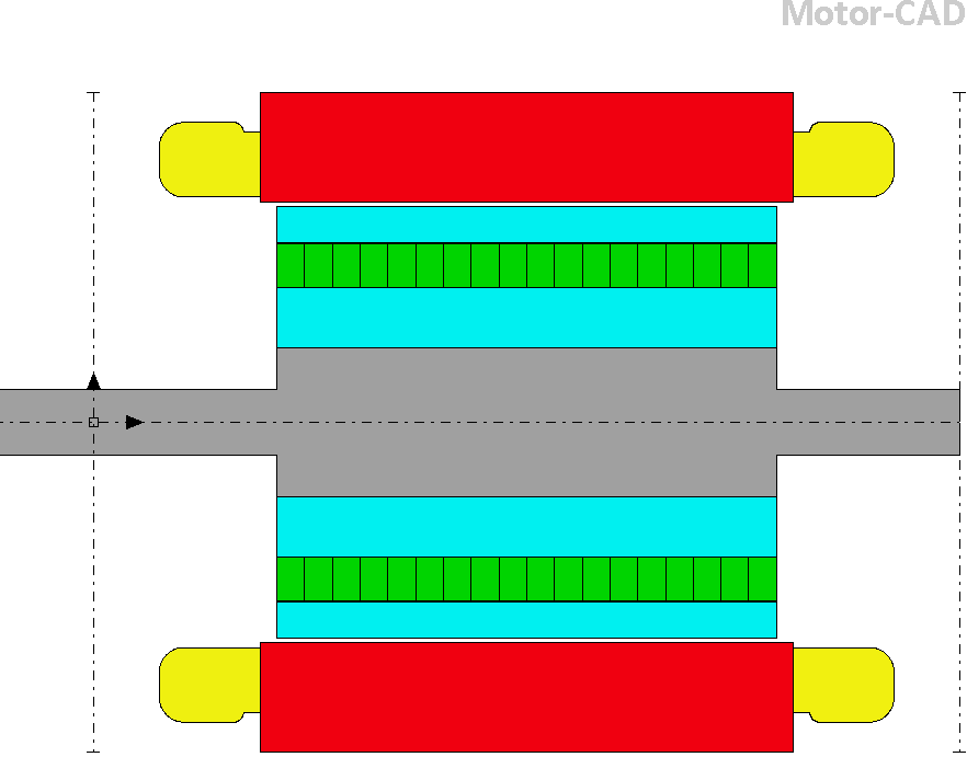
The geometry tab has options to edit the radial and axial geometry parameters. Right clicking on geometry field will show you in the model view which geometry object this geometry parameter corresponds to. These parameters can be used in scripting and in sensitivity studies to analyze a range of values for a given parameter and see how this affects the motor performance.
Geometry Radial View
Axial View
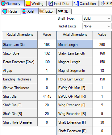
3D View
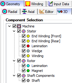
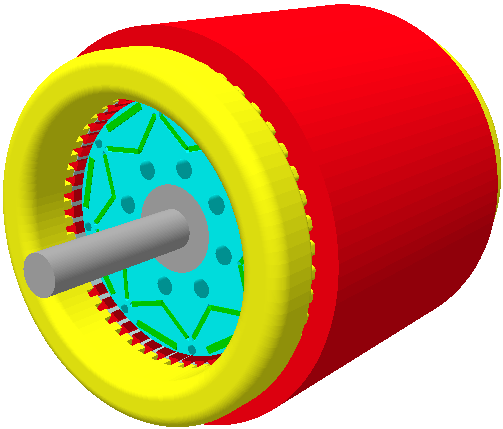
Motor Winding Configuration
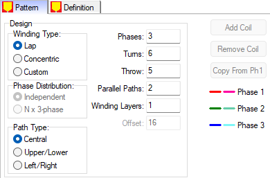
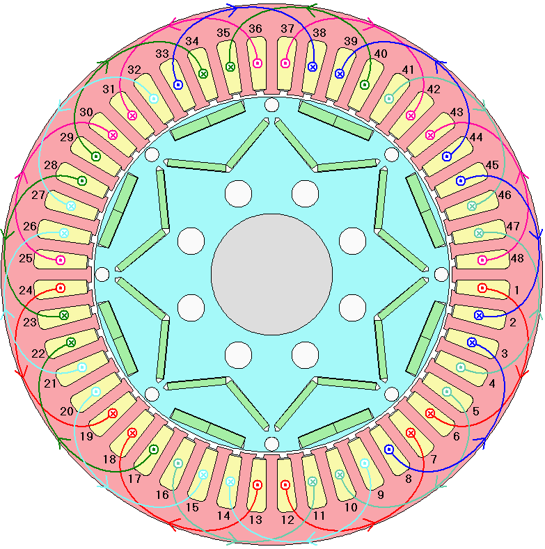
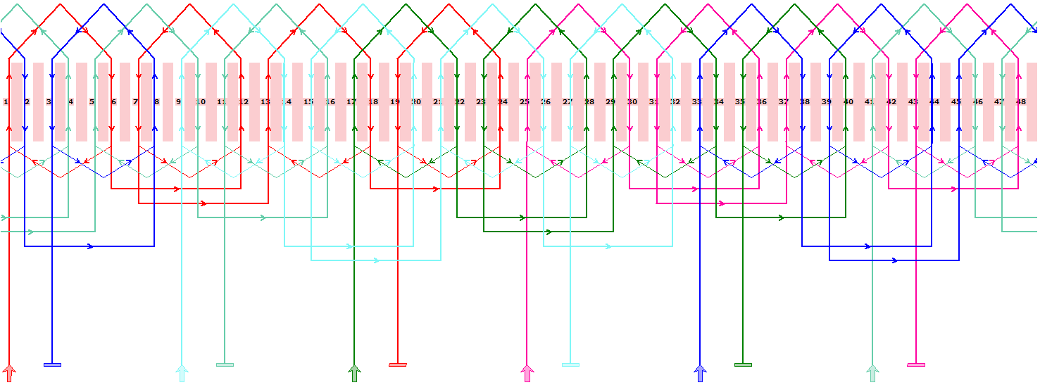
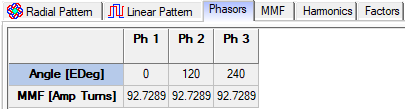
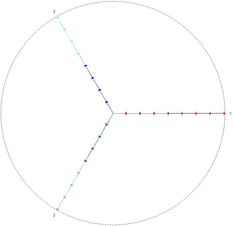
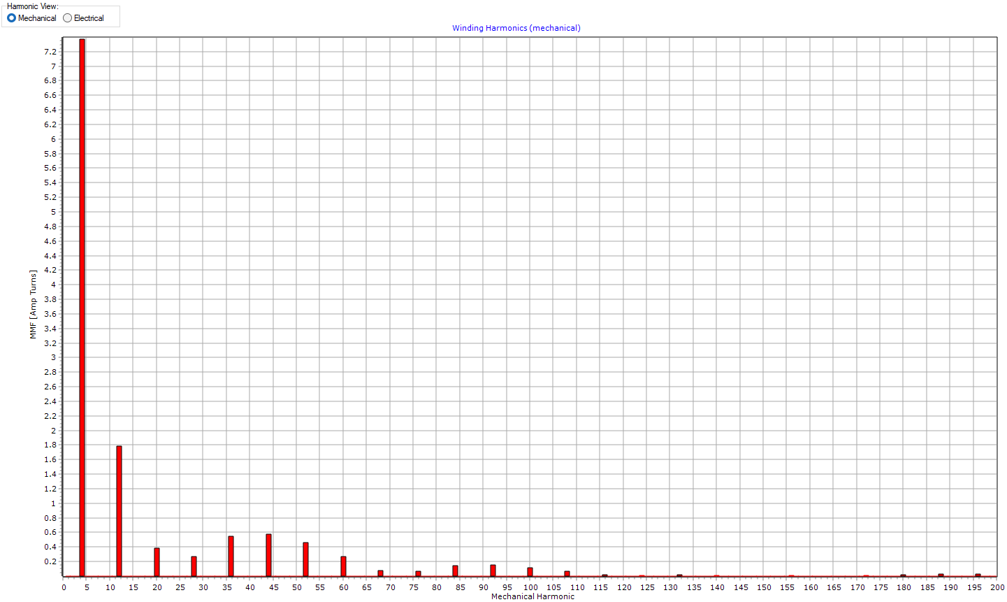
The Motor Winding tab includes settings for the winding pattern (Design, Phase Distribution, Path Type, Phases, Turns, Throw, Parallel Paths, Winding Layers, etc.) and has tabs to show the winding as a Radial Pattern, Linear Pattern. Also, the winding tab has tabs to view the Phasor Diagram, MMF Waveform, Harmonics Distribution (Electrical and Mechanical).
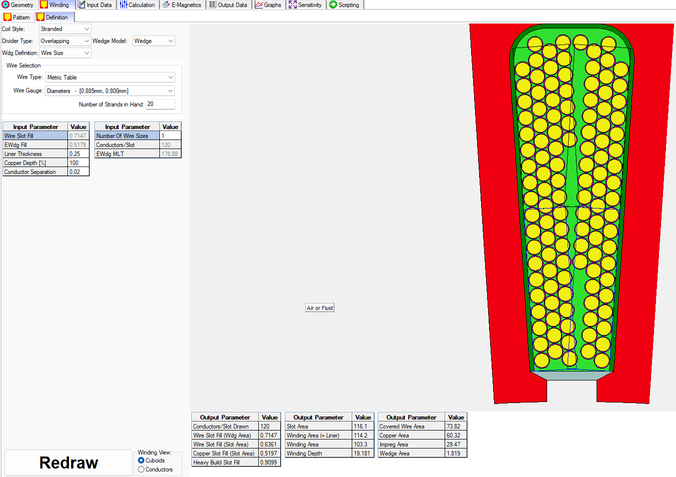
In addition, the Winding Tab includes a tab for the Winding Definition which includes settings for the
- Coil Style: Stranded or Hairpin
- Divider Type: Overlapping, Solid Divider (Rectangular-Side/Side), Air Divider (Rectangular-Side/Side), Solid Divider (Upper/Lower), Air Divider (Upper/Lower), Solid Divider (V Shape – Side/Side), Air Divider (V Shape – Side/Side).
- Wdg (Winding) Definition: Copper Slot Fill, Wire Size, Heavy Build Slot Fill.
- Wedge Model: Wedge, Wound Space, Air
- Wire Selection: Wire Type ( AWG, Metric, Diameter Input, Rectangular, SWG, Litz), and Wire Gauge (Diameter of wire including insulation, diameter of copper).
Illustrations of the Winding Tab, subtabs, and options for settings for the windings are shown below.
Winding – Pattern


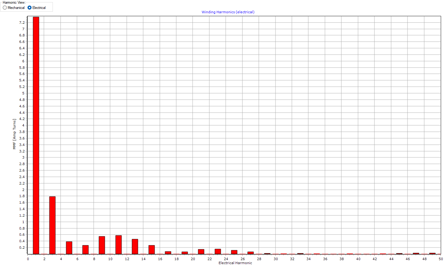
Mechanical harmonic frequencies equal the electronic harmonic frequencies multiplied by the pole pair number.
Winding – Definition
INPUT DATA
The Input Data tab contains three subtabs which are
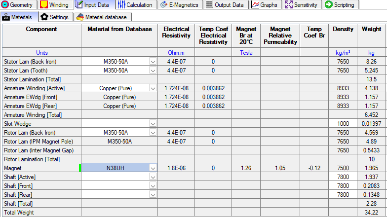
- Materials: Table showing the materials used in the model and corresponding to the physics selected.
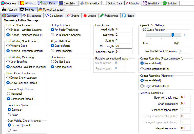
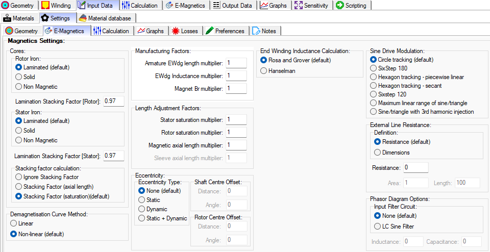
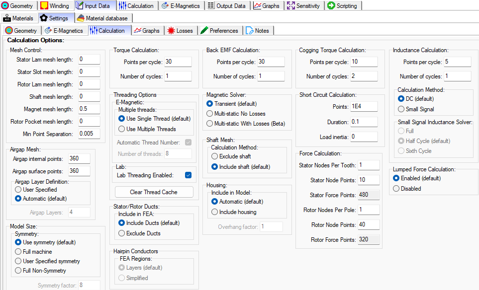
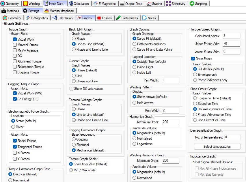
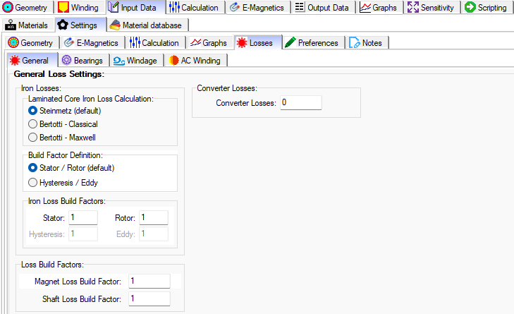
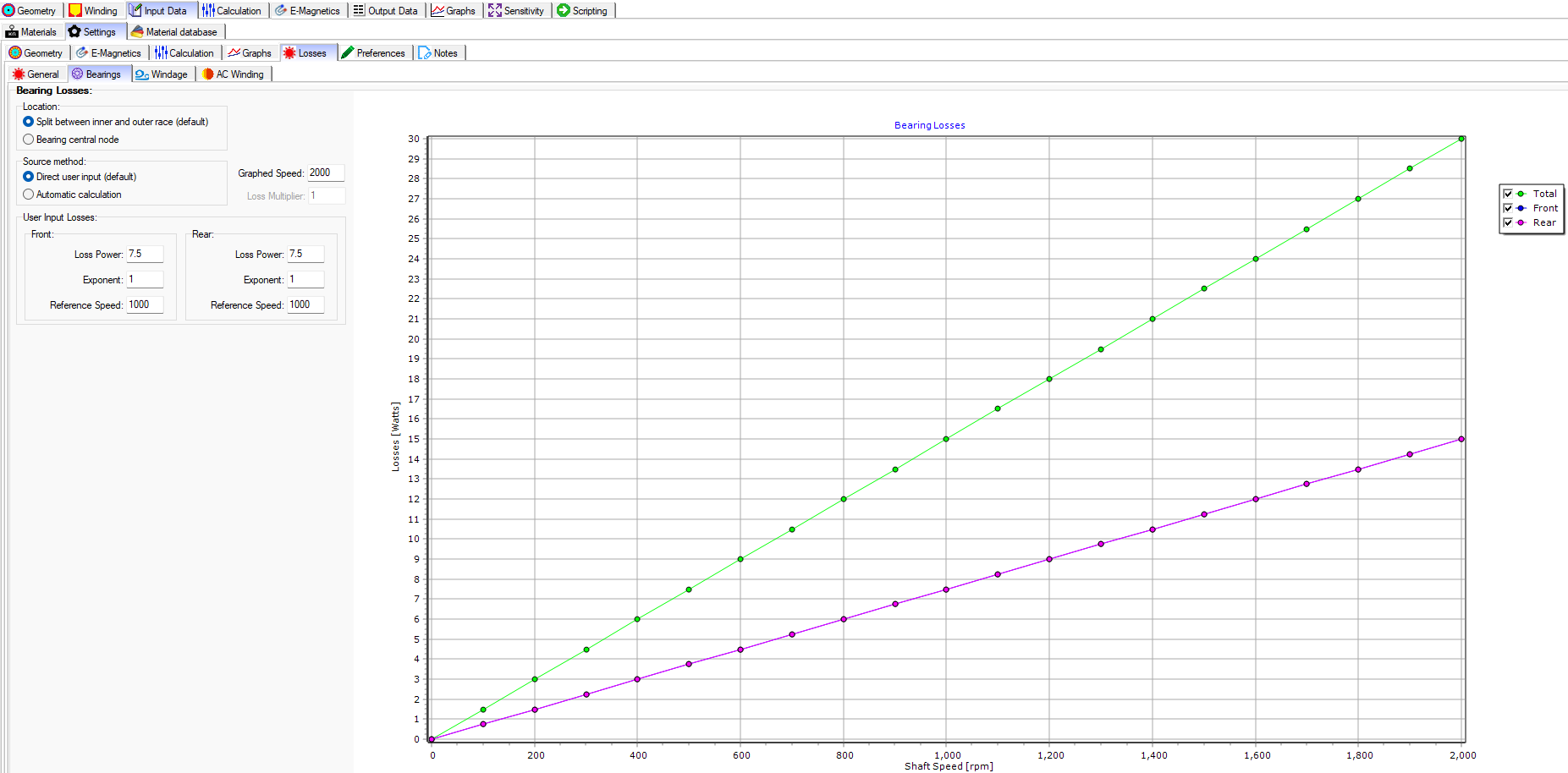
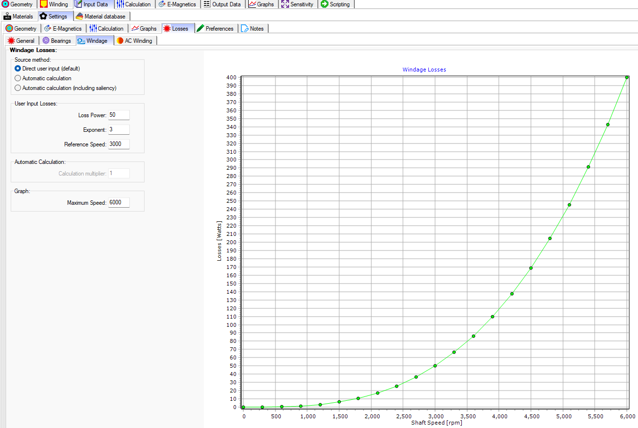
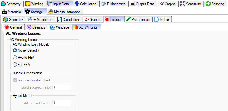
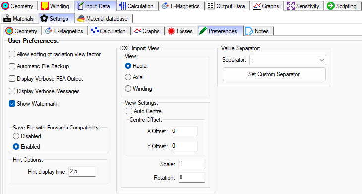
- Settings: Includes tabs for configuring options for Geometry, E-Magnetics, Calculation (mesh density, symmetry, etc.), Graphs, Losses (Iron, Build Factors, Converter, Bearings, Windage, and AC Winding) , Preferences, and Notes.
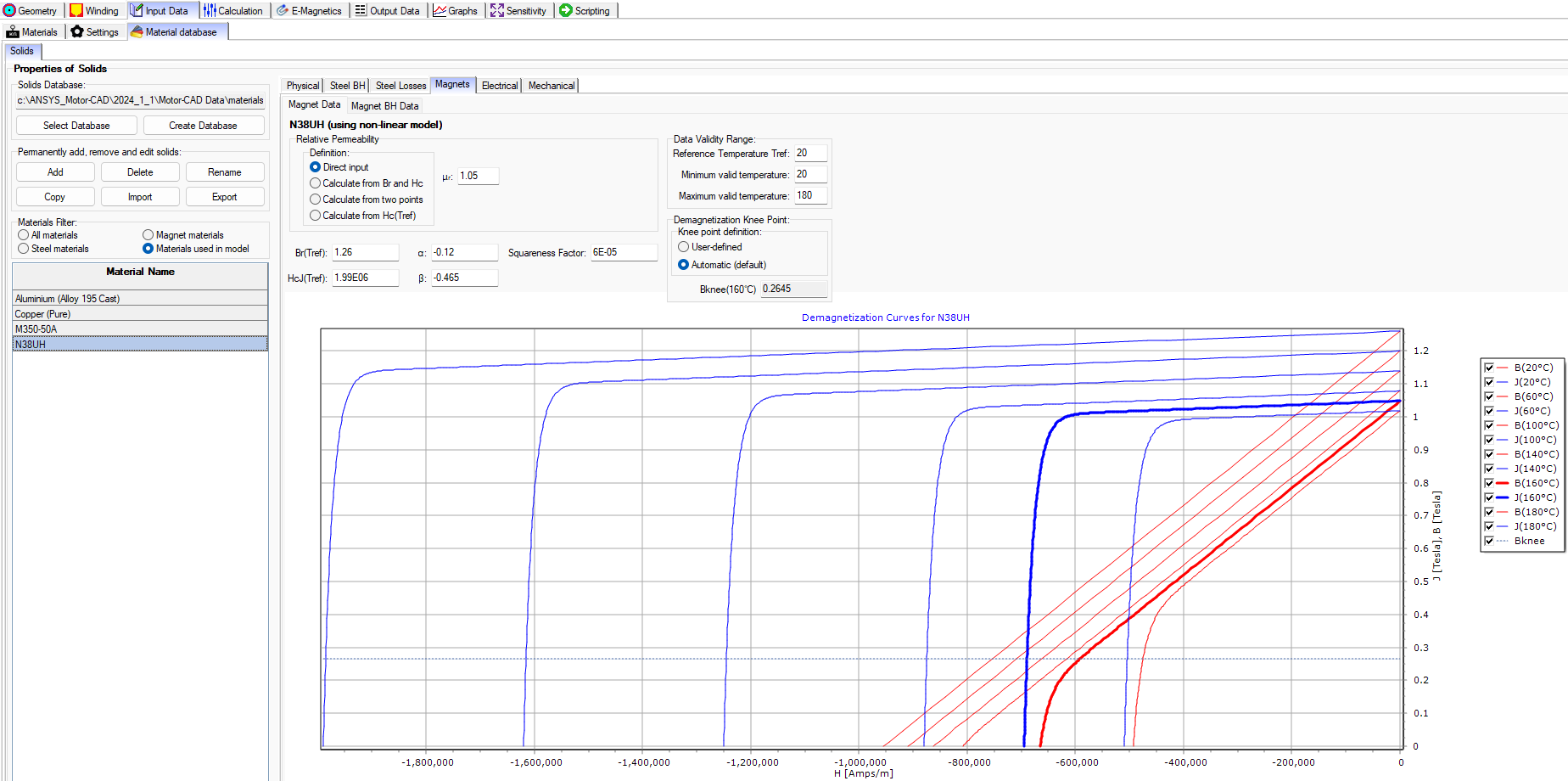
- Material Database: Includes options to view properties and graphs (BH curves, demagnetizing curves, etc.) for a selected material in the model.
Configuring these options properly allow to model an accurate representation of the motor.
Input Data – Materials
Input Data – Settings – Geometry
Input Data – Settings – E-Magnetics
Input Data – Settings – Calculation
Input Data – Settings – Graphs
Input Data – Settings – Losses – General
Input Data – Settings – Losses – Bearings
Input Data – Settings – Losses – Windage
Input Data – Settings – Losses – AC Windings
Input Data – Settings – Preferences
Input Data – Material Database – Solids
CALCULATIONS
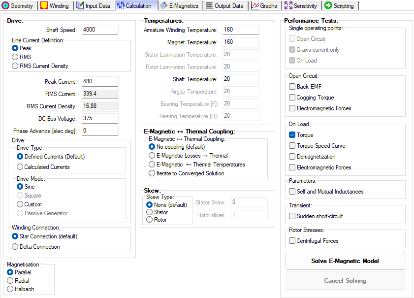
There are two levels of settings for Calculations. Level 1 is in the main tabs menu, and Level 2 is accessed via Input Data > Settings > Calculation.
Level 1: Options to set the Drive, Temperatures, E-Magnetic & Thermal Coupling, Skew, and Performance Tests.
Level 2: Options to set mesh control, Model Size (Symmetry), Threading, Magnetic Solver Type, etc.
E-MAGNETICS
There are two levels of settings for E-Magnetics. The first level is shown below and the second level is accessed via Input Data > Settings > E-Magnetics.
Level 1: There are three tabs
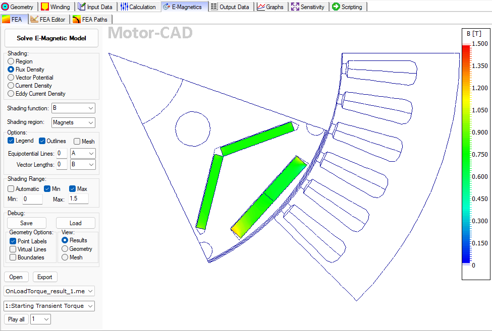
- FEA: Field plot options
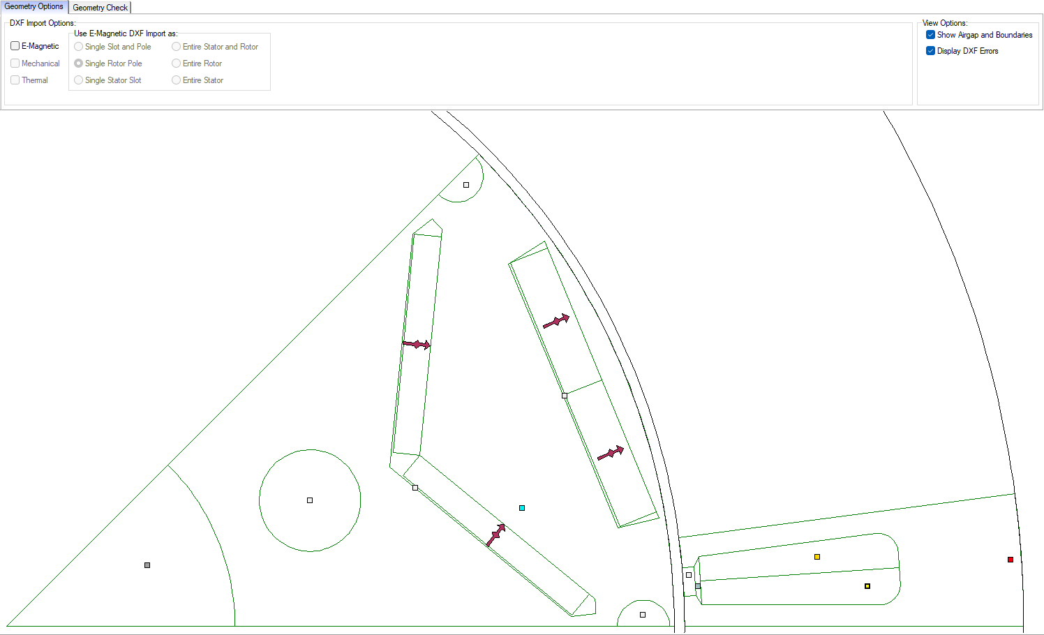
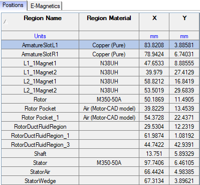
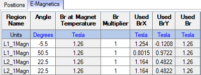
- FEA Editor: Options to edit positions of objects, and options to magnet Br value and angle orientation. Other options include DXF Import and Geometry Check.
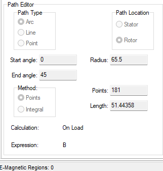
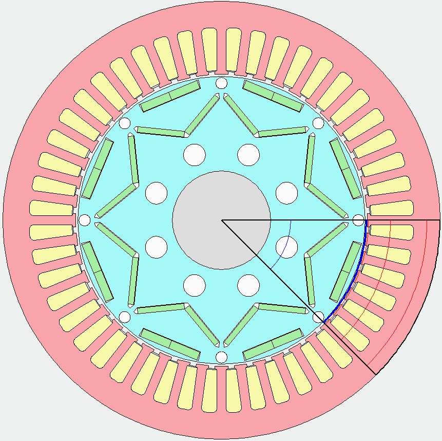
- FEA Paths: Edit and define FEA measurement paths used to calculate quantities from the Electromagnetic FEA simulation as it solves the model.
Level 2: There are options for the Magnetics Settings
- Core model
- Demagnetization curve method
- Manufacturer Factors
- Length Adjustment Factors
- Eccentricity: Type and Offset
- End Winding Inductance Calculation
- Sine Drive Modulation
- External Line Resistance
- Phasor Diagram Options
E-Magnetics – FEA
E-Magnetics – FEA Editor
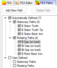
E-Magnetics – FEA Paths

OUTPUT DATA
The Output Data tab in the main menu contains the following tabs for options and settings to configure the:
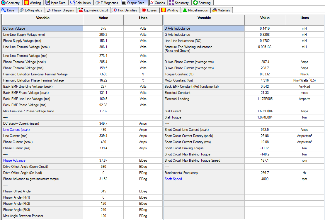
- Drive
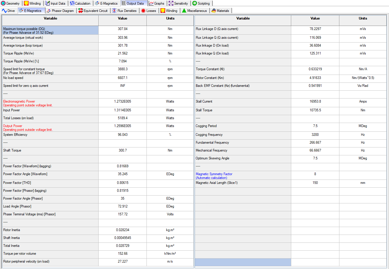
- E-Magnetics
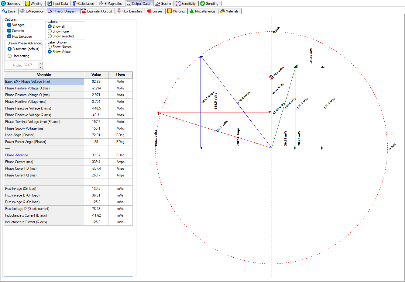
- Phasor Diagram
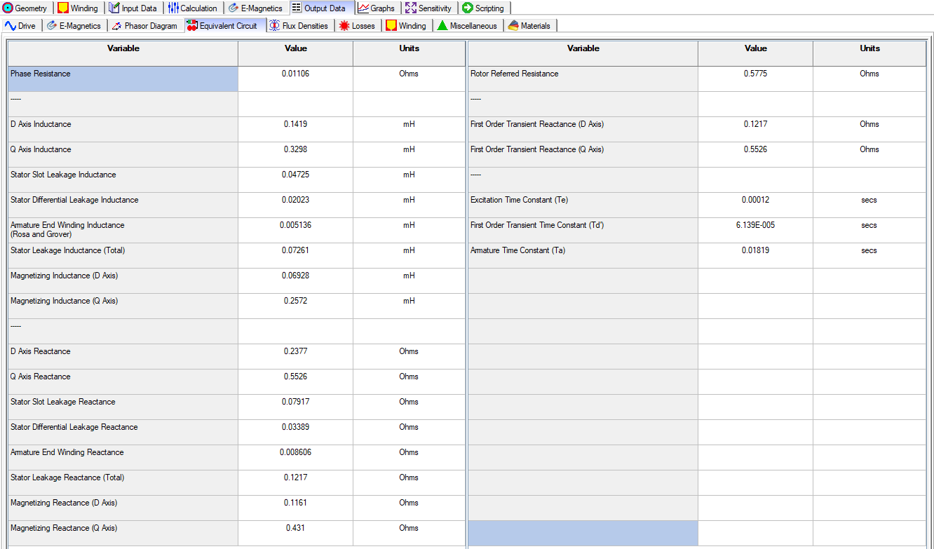
- Equivalent Circuit
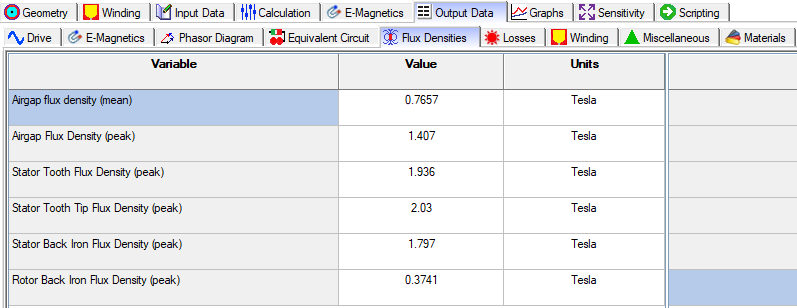
- Flux Densities
- Losses
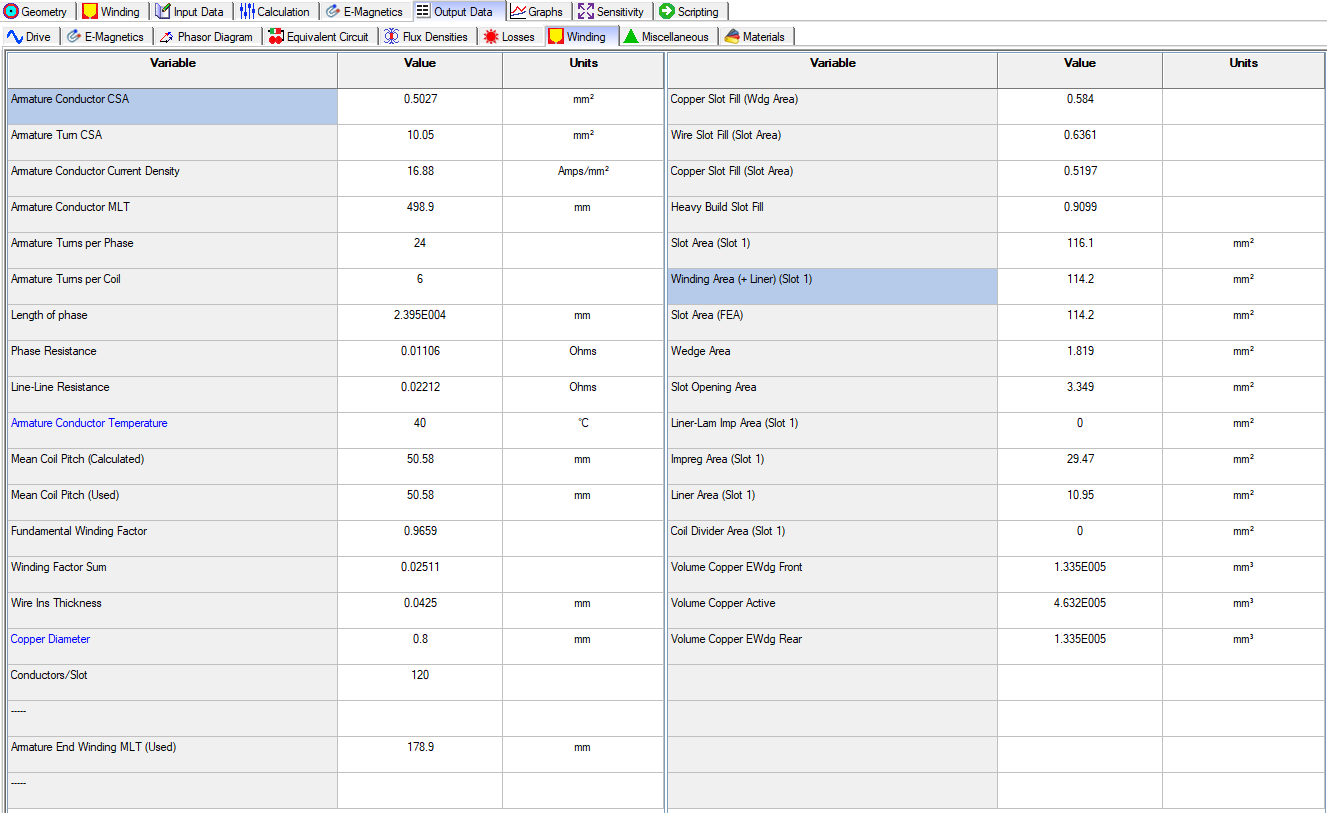
- Winding
- Miscellaneous: Provides values for the FEA Mesh Nodes, FEA Mesh Elements, and Airgap Mesh Layers Used.
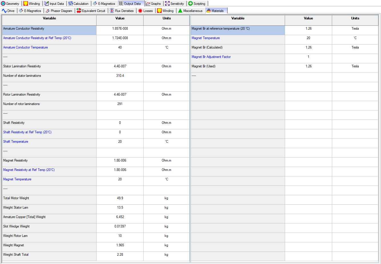
- Materials: Includes information of the material values used in the model.
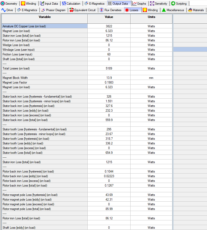
The following illustrations below show the contents of the tabs described above.
Output Data – Drive
Output Data – E-Magnetics
Output Data – Phase Diagram
Output Data – Equivalent Circuit
Output Data – Flux Densities
Output Data – Losses
Output Data – Winding
Output Data – Miscellaneous

Output Data – Material
GRAPHS
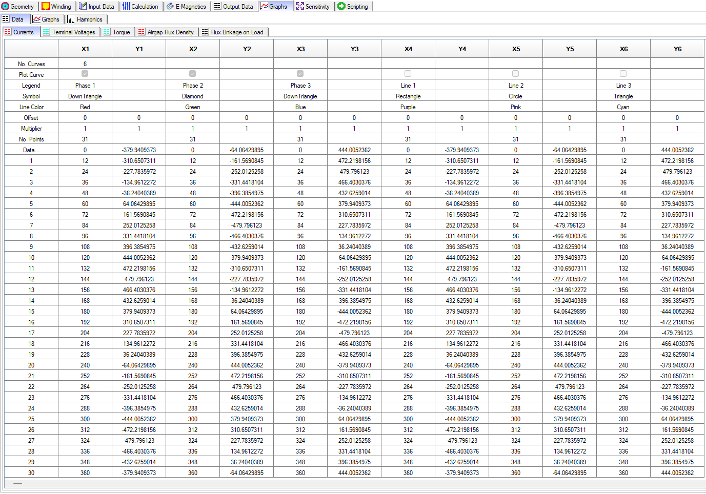
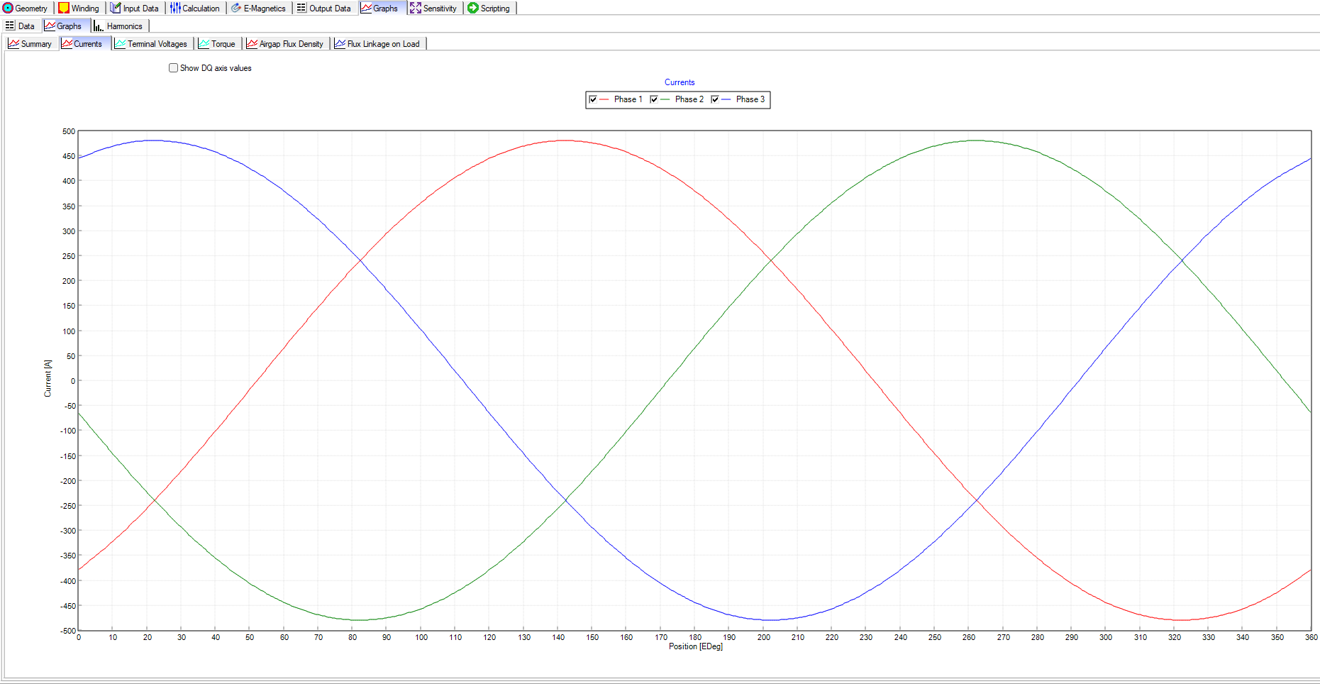
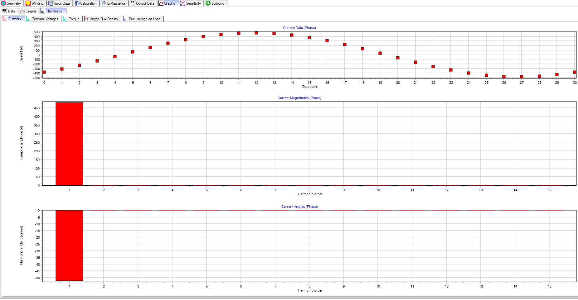
The Graphs tab provide results in the form of a Data Table, Plot, or Harmonics Bar Plot and the quantities available to view include:
- Currents
- Terminal Voltages
- Torque
- Airgap Flux Density
- Flux Linkage on Load
Output Data – Material
SENSITIVITY
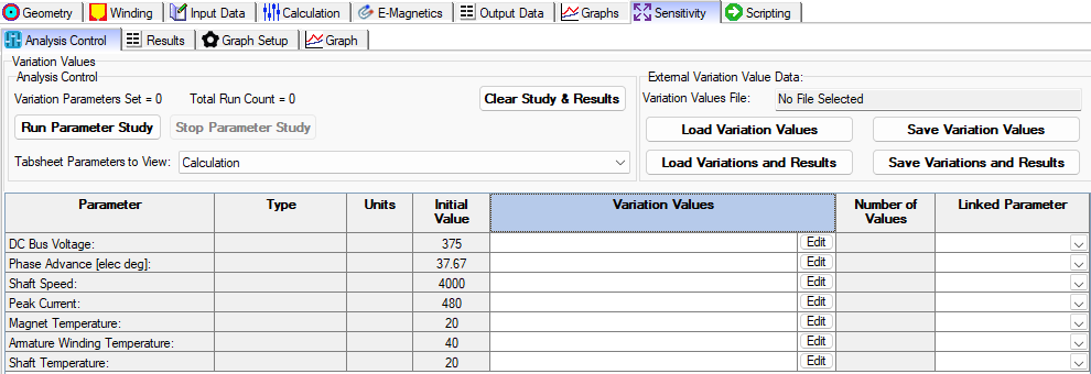
The Sensitivity tab allows you to sweep a parameter and see how this parameter affect the motor performance, and the quantities available to sweep are shown below. More information about this capability will be demonstrated in a later blog.
SCRIPTING
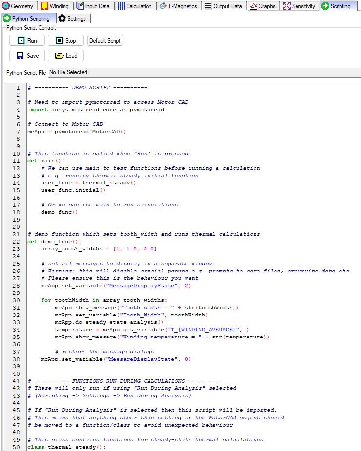
Scripting allows the user to have full control of the motor model parameters and all of the Motor-CAD settings. More information about this capability will be demonstrated in a later blog.