Contact Us
In this blog I discuss how to use the Mechanical physics module in Ansys Motor-CAD to analyze Rotor Stresses and Displacement by performing rotor endurance tests. Results from not including magnets and including magnets are compared.
MODEL
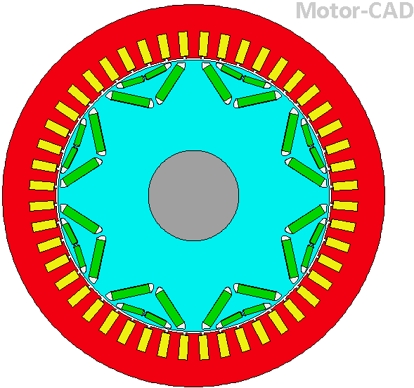
Open the IPM Motor Traction Mech tutorial project via the the path in the Motor-CAD installation folder,


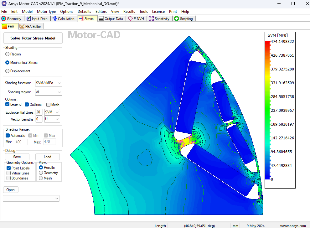
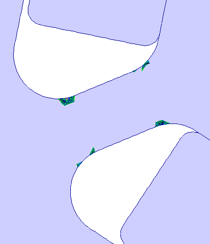
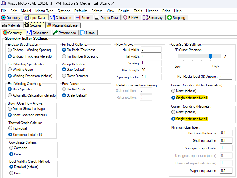
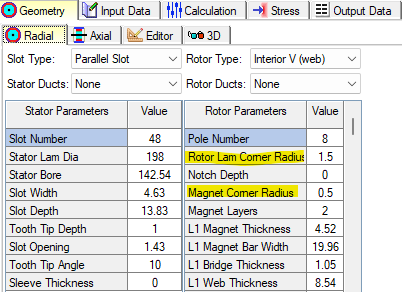
Sharp Corners in the magnets and rotor lamination openings will result in higher maximum stress results which will not be accurate if these objects have rounded corners as is usually the case in practice.
PHYSICS
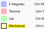
The Mechanical physics module is selected and for this physics the tabs are yellow as shown below.
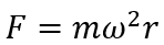
The magnets experience centrifugal forces as the rotor rotates and the magnets transmit these forces over the areas they are in contact with the rotor lamination which results in the stress. The forces and stresses are proportional to the square of the rotor rotational speed. The Rotor Stress test measures the endurance of the rotor and this test is usually done with the rotor operating a speed that is 20% over the rated speed.
Assumptions
- Zero stress in the axial direction (plane stress condition).
- Isotropic materials (same properties in the radial and tangential directions).
- Zero thermal stress (only centrifugal stress considered).
- No pre-imposed stress on the rotor lamination from the shaft (or rotor banding if it
exists)
Basic Mechanical Physics Review
- Stress: a quantity that describes the distribution of the internal forces within a body.
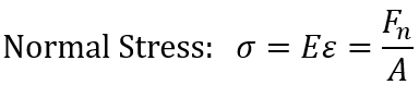
- Normal Stress: is the internal longitudinal force with respect to the cross sectional area this force is applied to divided by this cross section area.
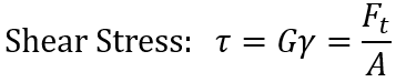
- Shear Stress: is the internal lateral force with respect to the cross sectional area this force is applied to divided by this cross sectional area.
- Von Mises Stress: an equivalent stress value that is used to determine if a given material will begin to yield, where a given material will not yield as long as the maximum von Mises stress value does not exceed the yield strength of the material.

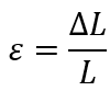
- Normal Strain: is a quantity that describes the deformations that occur in a body.
- Shear strain: the angle made when an object is under shear stress with respect to the object not stressed.
- Hooke’s Law (Force): force is proportional to displacement and the proportionality constant called Young’s Modulus, or Young’s coefficient represents stiffness.
- Hooke’s Law (Stress): stress is proportional to strain and the proportionality constant called Young’s Modulus, or Young’s coefficient represents stiffness.
- Material strength is a measure of the stress a material can withstand stress.
- Stress vs Strain: in the linear (elastic) region deformation is reversible. In the non-linear (plastic) region deformation is plastic.
- The ultimate strength is the maximum stress in the plastic region.
- Yield strength is the maximum stress the material can withstand beyond which stress is no longer elastic. Typically the yield strength is defined at the point of intersection of a line with slope equal to the initial slope of the stress vs strain curve but shifted in the strain direction by 0.2%.
- Ductile materials fail at the onset of plastic deformation.
- Brittle materials have a lower yield strength and fail at fracture.
- Fracture: the point at which a material fails.
- Resilience is a measure of a material to absorb energy when deforming elastically.
- Toughness is a measure of a material to absorb energy when deforming elastically.
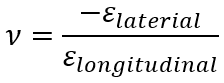
- Poisson’s ratio is a measure of how much a material will deform in the lateral directions when applying a force in the longitudinal direction with respect to a cross sectional area.
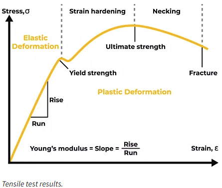
The Stress vs Strain curve above is analogous to the Magnetic Flux Density vs Magnetic Strength (BH) curve in electromagnetics. However, the curve above is an engineering Stress vs Strain since the original cross sectional areas are used to compute stress and the original lengths are used to compute strains. A more accurate Stress vs Strain curve is the True Stress vs Strain curve such that instantaneous cross sectional area and lengths are used to compute stress and strain, respectfully. The True Stress vs Strain curve is closer to a BH curve.
MATERIAL
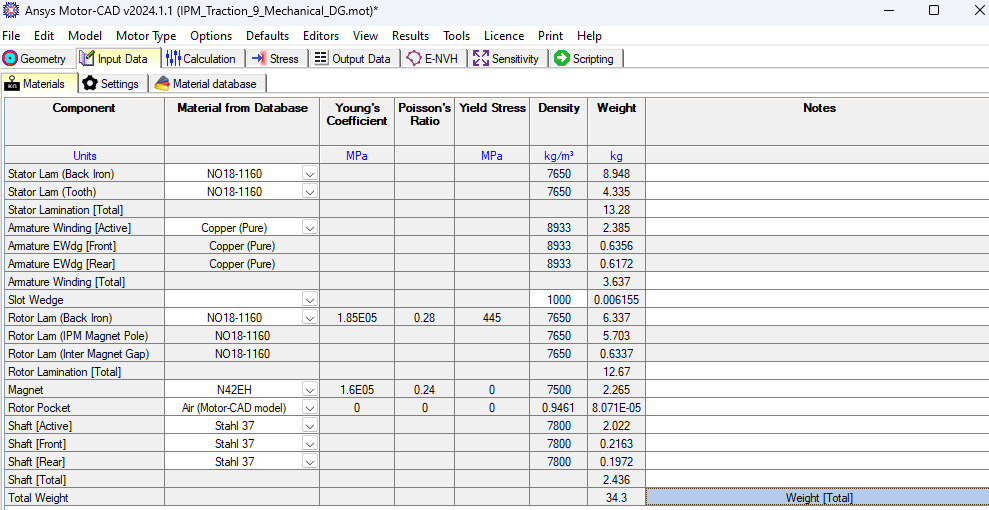
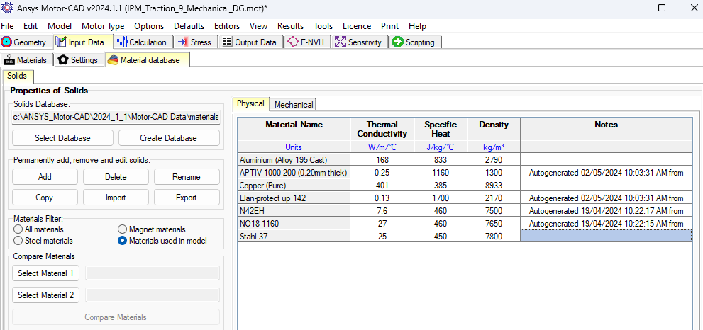
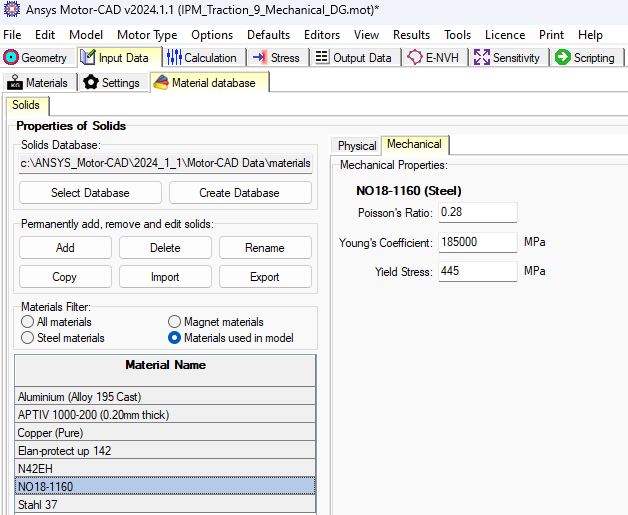
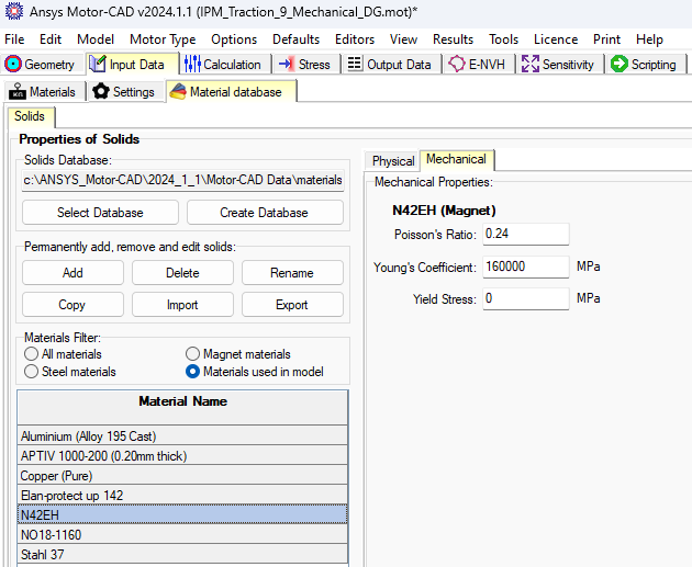
Select the tabs Input Data >> Materials and view the Materials used in the project and their mechanical properties. The mechanical properties can be edited via the Material Database >> Solids >> Mechanical tab, and Thermal properties of the material can be viewed via the Material Database >> Solids >> Physical tab.
Rotor Stress and Displacement
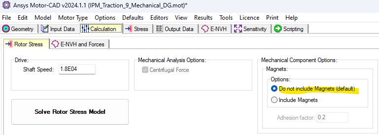
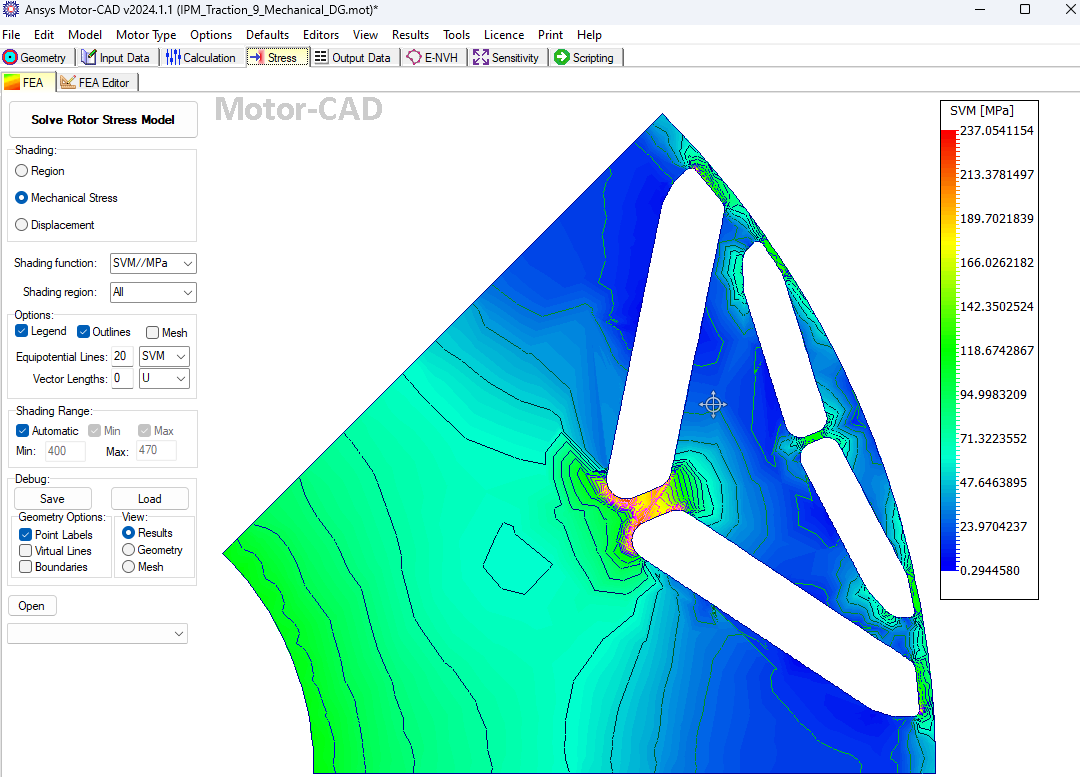
Here results are shown for rotor stress and displacement with magnets not included and then with magnets included for comparison.
Not Including Magnets
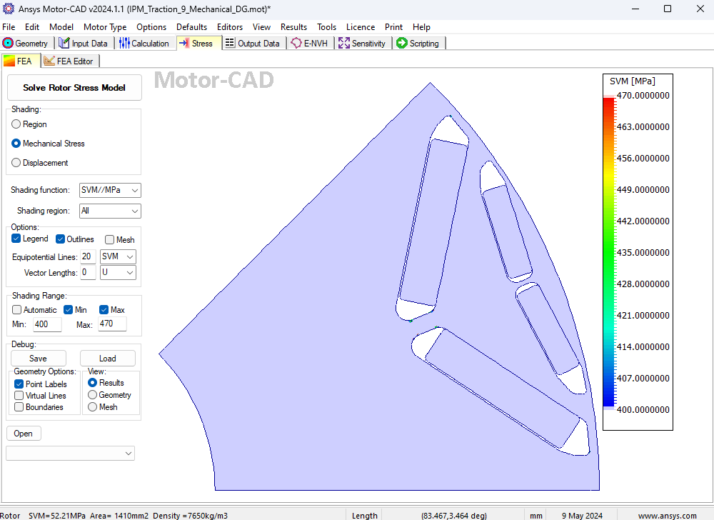
The rotor stress and displacement is less when magnets are neglected.
Including Magnets
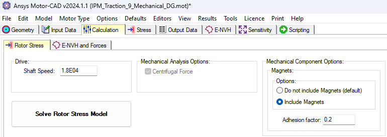
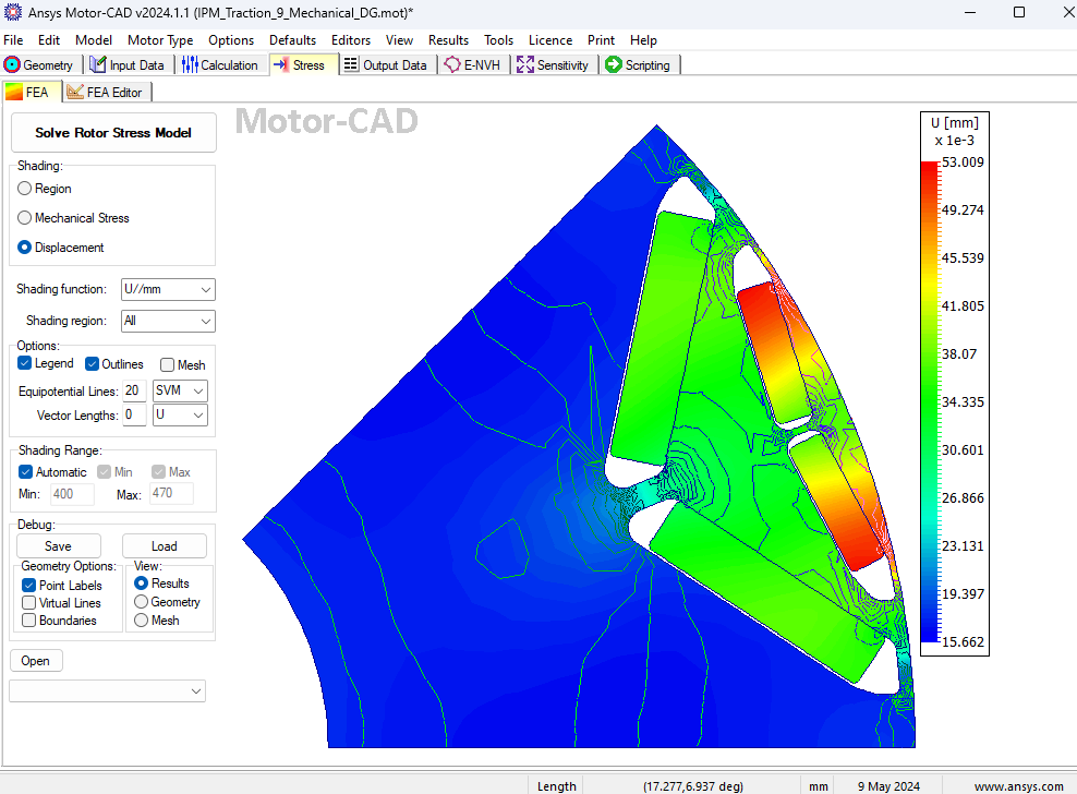
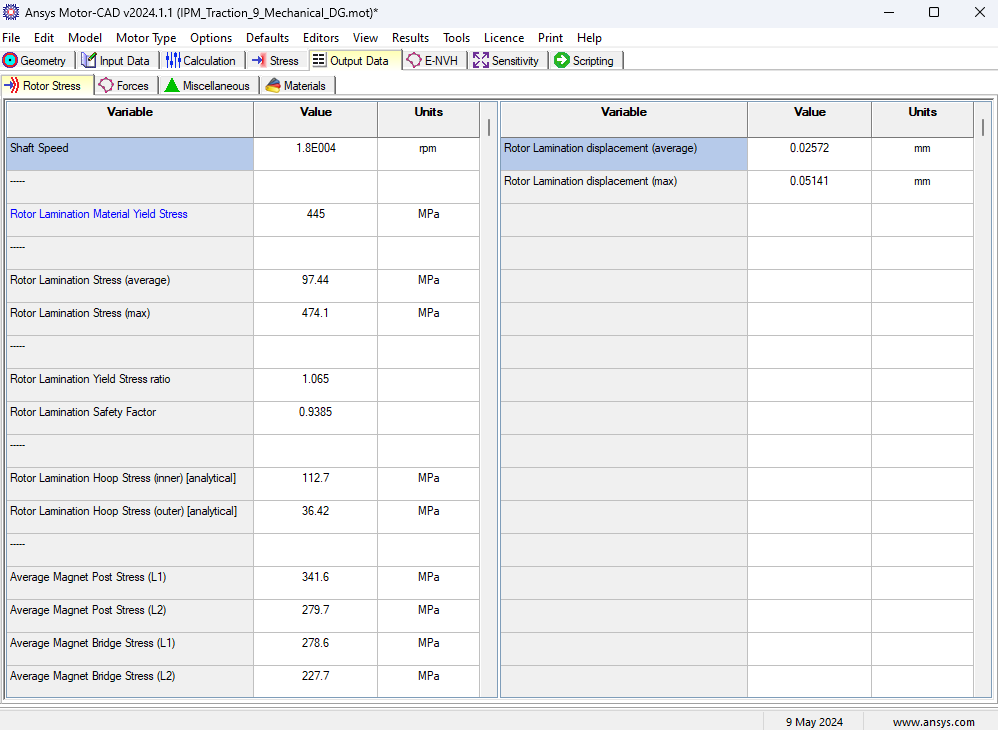
The rotor stress and displacement are about twice the value of the case with the magnets included. The adhesion factor is a fraction of the Young’s coefficient of the magnet material and measures the stiffness of the adhesion.