
 Contact Us
Introduction to Cable Elements in Ansys Mechanical
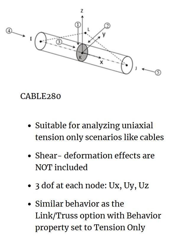
Many structures incorporate cables within their assemblies or rely on cables for support. Modeling cable elements in Ansys Mechanical using CABLE280 provides an efficient way to represent these components without unnecessary computational effort. This method can reduce the computation effort required to get the desired results. The CABLE280 element is defined below:
How to Model Cable Elements in Ansys Mechanical
To implement a cable elements model, use the following steps:
- In your preferred CAD software, draw a line between your desired attachment points. You can define the cross section of the cable using your CAD software or it can be defined within Ansys Workbench.
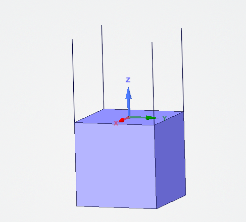
- Bring your design into Ansys Workbench and load it into a Mechanical model. To define cable elements in Ansys Mechanical, select the line bodies under Geometry and set their definition to “Cable.” This instructs Mechanical to use CABLE280 elements.
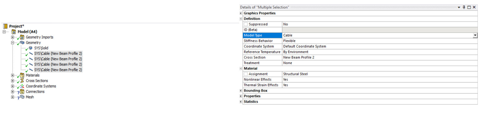
- From here you can set up your Mechanical Model like any other structural assessment. Then you can either run a Static Structural or Transient Structural. Different steps are required depending on which system is chosen. Key differences will be highlighted below:
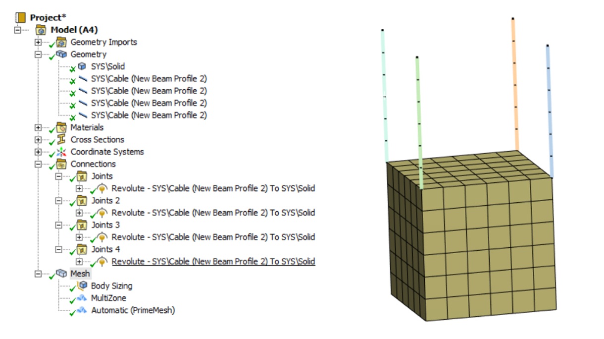
Static Structural Analysis with Cable Elements
- Static Structural: Due to the nature of the cables, extra steps are required to prevent rigid body motion. To prevent this rigid body motion an APDL Command is required within model set up. The APDL command INISTATE will add an initial strain to the cable elements. This initial strain value needs to be selected carefully; you can verify the magnitude of the strain by checking the force reactions.
- Note: Preventing rigid body motion can be difficult with cable assemblies due to the highly flexible nature of these bodies. If issues persist using Transient Structural will be the best solution
Transient Structural Analysis with Cable Elements
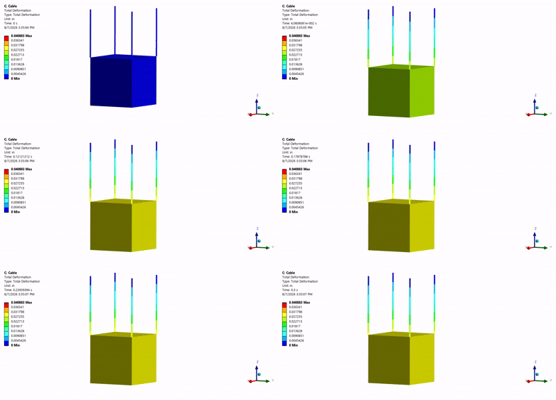
- Transient Structural: No additional objects are required to be added to your analysis set up with this system. Careful consideration is needed to select the correct time duration. Certain geometries can be prone to oscillation. As demonstrated below:
Conclusion:
For assemblies that utilize cables within their assembly, using cable elements can increase model accuracy and efficiency. As demonstrated here it is simple to integrate these elements into your model. Additional thought in the initial model set up will be required to determine if Transient Structural will be required for the assessment.
Simplify Structural Simulation with Ansys Mechanical
Using cable elements in Ansys Mechanical can help reduce model complexity while capturing the structural behavior of cable-supported assemblies. Whether you’re evaluating static loading conditions or transient structural responses, selecting the appropriate modeling approach is essential to obtaining meaningful results.
Connect with SimuTech Group’s structural simulation experts to explore Ansys Mechanical capabilities and improve your FEA workflows.

Eric Probst
Staff Engineer – Structures, SimuTech Group
Eric Probst is a Staff Engineer at SimuTech Group with experience in finite element analysis, structural simulation, and mechanical design. His background includes aerospace structural analysis, FEA project leadership, analysis procedure development, and technical mentorship. He previously worked as an FEA Team Lead and Senior Failure Analysis Engineer and holds a B.S. in Mechanical Engineering from Arizona State University.