

 Contact Us
Tipping Analysis Introduction
Telescoping task light stands used for photography, videography, portable lighting, and event production are especially vulnerable to wind-induced instability because they combine a narrow base with a tall, flexible structure and a relatively large projected area. From a Computational Fluid Dynamics perspective, several design challenges can be evaluated directly. These include aerodynamic drag on the mounted light fixture, vortex shedding around cylindrical support sections, fluctuating side loads caused by gusting winds, and flow separation near joints and clamps. CFD can also help quantify overturning moments generated by wind forces at different extension heights and orientations. In many cases, transient wind loading rather than static loading becomes the dominant factor controlling tipping risk and overall stand stability.
Engineering Solutions for Wind Tipping Resistance
Engineers commonly address these wind-related challenges through both structural and aerodynamic design improvements. Wider tripod footprints and lower center-of-gravity configurations increase resistance to overturning moments. Ballast systems such as sandbags or weighted bases are frequently used to improve stability in outdoor environments. Aerodynamic modifications can also reduce drag forces acting on the stand and attached equipment. Examples include streamlined light housings, perforated reflector panels that allow partial airflow passage, and reduced frontal area designs. Designers may also optimize telescoping tube diameters and spacing to reduce vortex-induced oscillations. In some cases, damping features are introduced to minimize dynamic motion caused by turbulent wind fluctuations and repeated gust loading.
Using Ansys Fluent to Evaluate Design Solutions
Ansys Fluent can be used to rapidly evaluate many of the engineering concepts of our tipping analysis before building physical prototypes. A Fluent CFD model can predict flow around telescoping poles, mounted lighting equipment, and support structures.
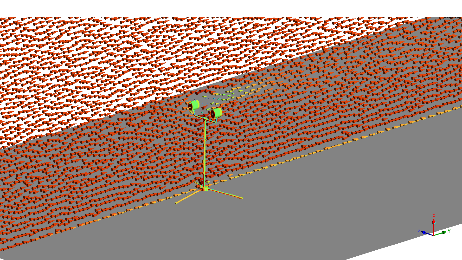
Engineers can evaluate drag coefficients, pressure distributions, wake formation, recirculation regions, and transient aerodynamic loading under varying wind speeds. Parametric studies can compare multiple stand geometries, extension heights, orientations, and leg concepts efficiently. Simulations provide valuable early-stage insight into flow behavior and help identify designs with improved resistance to tipping in high-wind operating conditions. For example, parametric studies can display the relationship between product mass required to resist tipping moment and input factors.
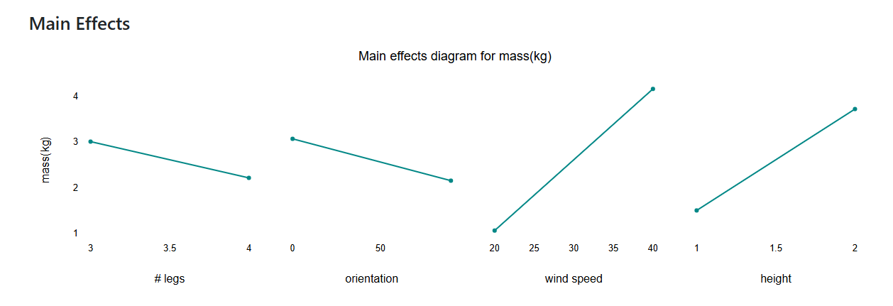
Simulation Approach and Tipping Analysis Objective
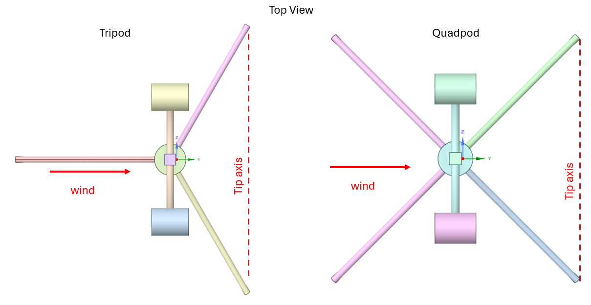
Tipping occurs when the aerodynamic drag moment exceeds the anti-tipping moment generated by the weight (mass) of the product. The product is assumed to begin tipping over an axis that connects the back two feet when orientated as shown below in the top views of both the tripod and quadpod leg configurations.
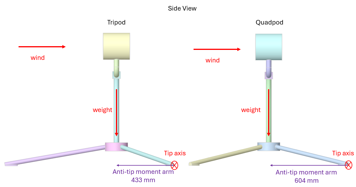
Tipping is assumed to not happen if the weight of the product multiplied by the anti-tip moment arm exceeds the aerodynamic drag moment. The anti-tip moment arms are displayed below in the side views of both leg configurations.
The goal of the simulation is to calculate the aerodynamic drag moment on the product and to calculate the minimum weight (mass) of the product to prevent tipping.
Thought Map
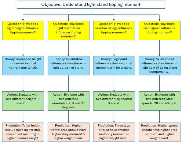
A thought map of modeling characteristics is generated to organize and represent ideas, concepts, or information in a structured way. The thought map below shows the simulation study’s objective and the questions asked to address it. Each question is followed by a theory, an action, and a prediction.
Product Map
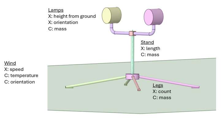
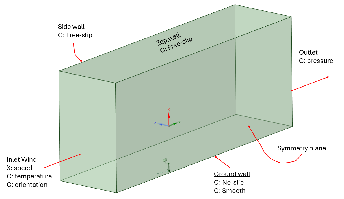
A product map is generated to list and categorize product and simulation features. A product map indicates factors that correspond to theories/actions in the thought map. The images below show product maps of the light stand and the wind tunnel. A category is underlined. Variable factors are prefaced with an X, and constant factors are prefaced with a C. The geometry of the task light is assumed to be symmetric about the vertical midplane.
Fluent Simulation Mesh
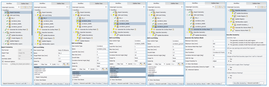
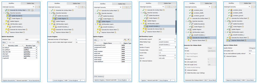
In our tip analysis of the telescopic light stand, the simulation domain is meshed for flow simulation using Fluent Meshing Mode. The watertight workflow is employed to complete all the necessary steps. This workflow requires a watertight geometry from the geometry preprocessor. The workflow contains task steps that include local surface and global surface mesh sizes, region classification, boundary classification, boundary specification, and volume meshing.
Fluent Simulation Setup
Fluent flow simulation setup specifies steady-state solver, air material properties, and boundary conditions. For this simulation a Named Expression called “windspeed” is used to specify the inlet air velocity for 20 mph and for 40 mph. The outlet is specified as a zero-gauge pressure boundary. The ground and task light walls are specified as no-slip walls. Tunnel wall, tunnel ceiling, and tunnel midplane are specified as symmetry planes.
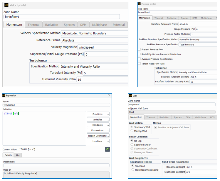
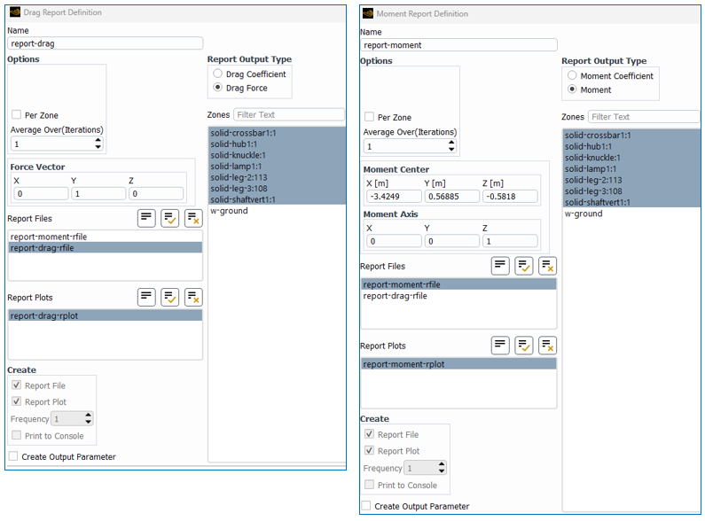
A Drag Report Definition is employed to monitor and record the total aerodynamic (drag) force exerted on the product surfaces. The force vector is in the Y-direction.
Likewise, a Moment Report Definition is employed to monitor and record the total aerodynamic moment exerted on the product surfaces about a moment axis (center). The moment center corresponds to the tipping axis at the downwind feet. The Y value differs from tripod to quadpod configurations. The direction of moment axis is in the Z-direction.
Fluent Simulation Results
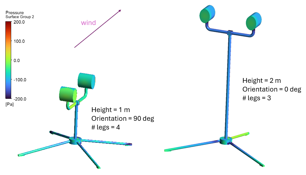
One of the key results in our tipping analysis is the normal pressure distribution on the product surfaces. The normal pressures and the surface normals are used to generate the normal forces on the product. High pressure can be seen on the lamp surfaces that face upwind.
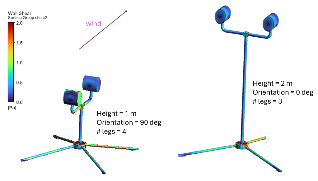
Another key result is the wall shear stress distribution on the product surfaces. The shear stresses and the surface normals are used to generate the shear forces on the product. High wall shear can be seen on the lamp surfaces that face perpendicular to the wind.
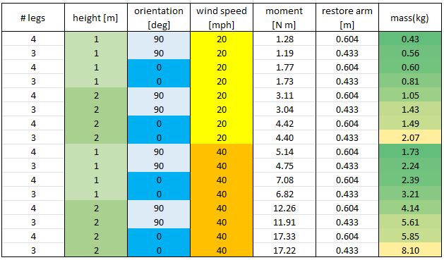
Monitors of force and moment provide Design of Experiments data that are used to generate Analysis of Good tables and Pareto diagrams.
The Analysis of Good Table below shows the ranking of product masses blocked by wind speed. It shows the stronger significance of product height over lamp orientation. It also shows the weaker significance of leg count.
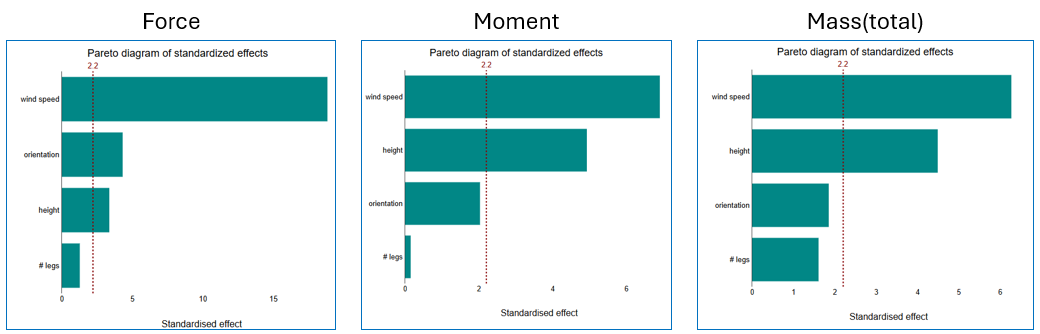
The force and the moment Pareto plots below indicate that wind speed is the most significant factor on force and that the leg count factor is the least significant.
The minimum mass (weight) to prevent tipping is calculated from the moment arm length. The mass Pareto still indicates that wind speed is the most significant factor; however, the leg count is not as insignificant due to the difference in anti-tip moment arm length.
Video of Tipping Analysis Simulation Setup
Improve Product Stability with Ansys CFD
Telescoping light stand design seeks to reach product requirements which includes robust tip over resistance. SimuTech Group’s fluids team helps engineering organizations use Ansys simulation tools like Fluent to evaluate complex lamp and stand designs to make more confident design decisions earlier in the development process.
Whether you are working on lighting equipment, photography equipment, videography equipment, or audio equipment SimuTech Group can help you build stronger simulation workflows with Ansys Computational Fluid Dynamics tools such as Fluent.

Brian Peschke, Lead Engineer – Fluids
Brian Peschke is a mechanical engineer with more than 20 years of industrial experience specializing in computational fluid dynamics and the analysis of fluid and thermal performance. At SimuTech Group, he helps engineering teams apply CFD simulation to close knowledge gaps, troubleshoot complex performance challenges, and make more informed product-development decisions.


