Optimizing Printed Circuit Board Design & Performance
Many PCB design problems require alterations via component placement, trace routing, or the plane metallization itself, all of which prove difficult to manage on the bench.
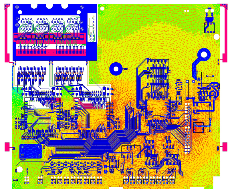
SimuTech Group’s engineers can quickly examine the full spectrum of printed circuit board-related electrical and/or frequency issues within minutes, and cut down the number of prototype cycles needed to produce a working design. These span areas as wide as DCIR analysis (even coupling to mechanical and thermal results), power integrity, signal integrity, EMI, and many more.