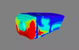
Ansys Motion is a third-generation engineering solution based on a sophisticated multibody dynamics solver, now available within the Ansys Mechanical Interface.
Ansys Motion is a fully integrated simulation environment that can be used to model Multibody Dynamics (MBD) of components and systems. Moreover, Motion employs a single solver to perform fast and accurate analysis for both stiff and flexible bodies, simultaneously.
In addition, Ansys Motion enables quick and precise analysis of rigid and flexible bodies and calculates accurate evaluations of physical events through an analysis of the whole mechanical system.
Performance of the system, stress-safety analysis, heat transport, vibration, and fatigue are all important. For multibody dynamic system design, Ansys Motion is the most robust and comprehensive simulation solution available.

Ansys Motion is a versatile multibody dynamics-based next-generation engineering solution. It permits the study of stiff and flexible bodies quickly and accurately using a single solver system. Performing system motion performance, stress safety analysis, vibration analysis, and fatigue analysis throughout the design phase, helps reduce time-to-market in a variety of industrial applications. The integrated GUI of Motion provides a robust modeling environment for component and system analysis, which may be done independently or simultaneously, bringing up new possibilities during design and analysis.
Ansys Motion Key Features

Using shared memory parallel processing (SMP) and massive parallel processing (MPP) environments, you can simulate quicker and more effiecntly.

Components can be represented as a single entity made up of part and mesh files. Part and mesh files are handled and kept separately, allowing data to be resued in different models.
A post-processor allows for quick animation of a system with complex geometries.

A parametric generalized coordinate system is used to formulate the governing equations of motion. Joints, primitive, restrictions, bushing, contacts, and a user-defined function expressions connect the rigid bodies. Surface-to-surface contact that is smooth is encouraged. Piecewise triangular patches or a NURBS surface can be used to depict the surface.

The solver was created with the intention of combining the two fields of MBD and finite element (FE) analysis. Consequently, there are multiple connecting elements of rigid and flexible bodies. Because the system utilizes the numerically stable implicit integration method, the system is free from numerical noise and is very smooth and reliable.

A finite element program, such as Ansys, is used to extract mode forms. The linear combination of the mode forms expresses mechanical and deformation. The computation time is short because it solves reduced modal coordinates. Modal flexible bodies and full nodal flexible bodies can be simply switched, and other stiff and nodal flexible bodies can be solved.
It is possible to recreate natural frequencies and modes. The static correction mode will provide a more accurate solution of a modal flexible body for body eigenvalue analysis.
In Ansys Motion, fatigue analysis is merged into one process. The load and stress histories are generated simultaneously by the Ansys Motion solver. In the Ansys Motion post-processor, the fatigue life can be directly displayed.
The system’s input and output in the Ansys Motion model and Simulink file in MATLAB must be defined.
The function mockup interface (FMI) allows co-simulation of an Ansys Motion model with other tools that also support FMI.
Ansys Motion’s FMI is only available as a slave simulator. The system’s input and output within the Ansys Motion model must first be defined.
Under varying driving situations, the Ansys Motion Drivetrain Toolkit can examine the noise, vibration, and harshness (NVH) characteristics of drivetrain systems.
It can do analysis on everything from the first design concept to comprehensive production models. Waterfall color maps and order tracking data can be created in the same way as they would be in the real-world test environment. This advanced Multibody Dynamics (MBD) capability, in effect, enables accurate comparisons between simulation and reality.
A parameter study is possible due to predefined geometries for segment and path bodies. This is essential for comprehensive Multibody Dynamics (MBD) simulation.
The path body choosing step has been removed from the track assembly process. The path bodies are automatically found and utilized to put the track segments together. Contact surfaces are automatically defined for given geometries, eliminating the need to define them. To depict genuine shapes, the specified geometries have sophisticated modeling elements.
For established analysis situations, dedicated template and subsystem modeling tools can be utilized to construct chassis, suspension, steering, and wheels.
Users may simply assess kinematics and compliance (K&C) and ride and handling (R&H) scenarios due to the symmetric modeling capabilities and template-based procedures.
The Ansys Motion EasyFlex Toolkit does not require meshing prior to structural analysis, unlike traditional finite element analysis.
Because complicated 3D CAD meshing is not required, it makes flexibility modeling accessible to all users, including those who are unfamiliar with meshing technology. The strain and tension of machine parts with diverse shapes can be estimated in minutes using the Ansys Motion EasyFlex Toolkit.
The ACIS kernel is used to develop Ansys Motion pre-processors; .sat, ,sub files can be read directly. Other CAD data files will need to be translated using the appropriate CAD translator.