fbpx


Ansys Clock FX

Ansys Clock FX allows you to calculate clock jitter with variation on a full SoC, and control the effects of supply noise variation.


SimuTech-Group-Jitter-Analysis-Software-Semiconductor-VDD-Drop-and-Mesh


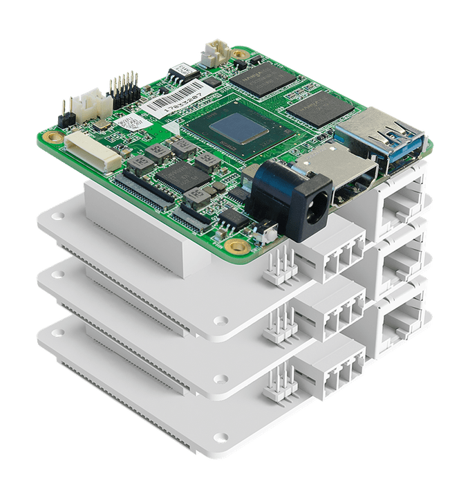
Microcontroller-single-board-computer-multi-core-platform-singleboard-software-SimuTech-Group


Electro-Thermal Design of Semiconductors & Power Converters for EPS Architecture


SimuTech-Group-Jitter-Analysis-Software-Semiconductor-SoC

SoC incorporates Multiple Processes, Voltages, Temperature Corners and Scenarios.

Line-Break-Dark-Blue-Simulation-Engineering-Experts-SimuTech-Group


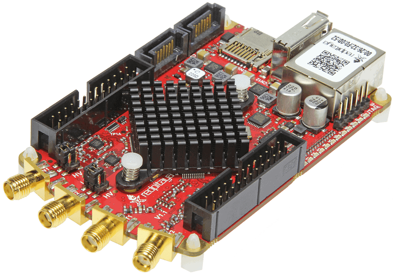
Electronics-PC-Keyboard-hdmi-optimization-SimuTech-Group

Clock FX (SoC Software) mines the dynamic voltage drop on the clock network produced by RedHawk-SC to calculate clock jitter with SPICE-level accuracy. In addition, the software also accounts for accurate multi-voltage analysis and simulates the delay impact of supply variation on the clock paths.
Voltage-Drop-Power-converters-electric-power-quality-ac-power-SimuTech-Group
  • Clock FX (SoC Software) handles transistor level effects such as voltage drop and ground bounce separately.
  • This enables accurate timing at ultralow voltages where margins are razor thin and variability is severe.
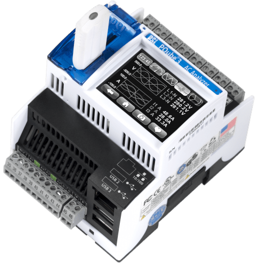
Electric-Spectrum-analyzer-SimuTech-Group
  • Clock FX (SoC Software) automatically identifies and simulates all the clock paths in the design using standard cell models or transistor-level SPICE models.
  • Its full waveform propagation provides the accuracy needed to get reliable results at ultralow voltage and advanced processes.
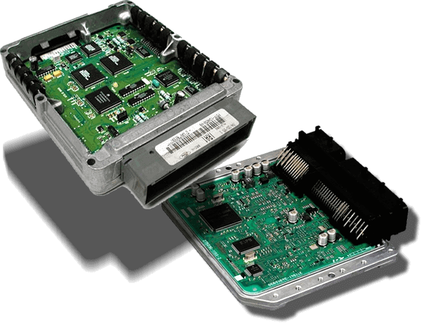
Car-Engine-control-unit-electronic-control-unit-repair-SimuTech-Group


  • Clock FX (SoC Software) is tightly integrated with the Ansys sign-off power analysis tool RedHawk-SC to obtain the dynamic voltage drop for simulation.
  • With the duo synchronized, the database generates a rich set of jitter reports covering various jitter types.
  • Clock FX (SoC Software) is threaded and distributed, dramatically reducing turnaround time and memory requirements, compared to Monte Carlo SPICE.
  • To study and compare the timing jitter (TJ) characteristics, our simulations deploy four core experimental schemes including hybrid mode-locking (HML), ML subject to opto-electrical feedback (OE FB), ML subject to all-optic feedback (AO FB), and ML subject to optical pulse train injection (OPTI).
  • These simulation parameters (if selected) are used to emphasize the role of the timing interaction of the pulses of master and slave MLL and to distinguish from continuous-wave injection.

Clock FX (SoC Software) leverages the SPICE transistor models and full waveform propagation to provide the accuracy needed to get reliable results at ultra-low voltage for advanced processes. Miller-capacitance and other effects are handled correctly, with no shortcuts.

Core database including (but not limited to):

Power supplies

  • Battery, Cell, Ground, Voltage Rail, Zero Volt Rail, Variable Input Voltage, DC Voltage Source, AC Voltage Source, Current Source, Fuse, Voltage Regulator


Input components

  • Push-to-Make switch, Push-to-Break switch, SPST switch, DPDT switch, Variable Resistor, Potentiometer, LDR, Thermistor (300R to 100K at 25°C), Phototransistor, Opto-Isolator, Crystal Oscillator (32.768KHz to 24.576MHz), SPDT switch, and DPST switch.


Passive components

  • Resistors, Resistor Packs, SIL resistors, Capacitor, Electrolytic Capacitor, Inductor, Transformer (Centre-tapped), Variable Capacitor and Variable Inductors.


Discrete semiconductors

  • Diode, Bridge Rectifier, NPN Transistor, PNP Transistor, N-Channel MOSFET, P-Channel MOSFET, N-Channel JFET, P-Channel JFET, Zener Diode, and Thyristor (SCR).


Logic gates

  • Clock, Input, Output, NOT (Inverter), AND, OR, NAND, NOR, XOR, XNOR, Schmitt Inverter, Schmitt NAND.  As well as Connectors including, Rail, Terminals, SILs, and DILs.


Integrated circuits (ICs)

  • 4000B series, 74LS series, 74HC series, 555 timer, Dot/Bar Display Driver, L293D half-H driver, ULN2003 and ULN2803 darlington array drivers, and Operational Amplifiers.


Output components

  • Bulb, Lamp, Buzzer, Loudspeaker, Motor, SPDT Relay, DPDT Relay, Flashing LED, Bi-Colour LED, Tri-Colour LED, 7-Segment Display, Dual 7-Segment Display, 16-Segment Display, Bargraph Display, 5×7 Matrix Display, Solenoid, and Core LEDs.