fbpx

Signal and Power Integrity Simulation Consulting

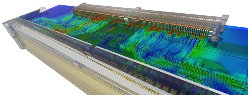
Improve your high-speed designs while optimizing signal integrity and power integrity (SI/PI) with SimuTech Group’s simulation consulting services. Leverage our industry expertise to optimize complex interfaces and transmission lines to push data rates higher.

Why Simulate Signal and Power Integrity?

As demands for higher data rates and smaller form factors increase, design challenges such as unacceptable bit error rates, electromagnetic interference, and manufacturing complications can compromise both signal and power integrity. Common root causes in the industry include:

  • Crosstalk from high-density routing
  • Reflections at interfaces
  • Unintended resonances
  • Routing and fabrication imperfections

Understanding and simulating these physical phenomena with SimuTech’s expert guidance are crucial for accelerating your design process, achieving higher transmission rates, and reducing field failures.

Signal Integrity Simulation Services

When considering complex interfaces that require analysis or optimization for signal integrity, SimuTech engineers use gold standard Ansys simulation software to import PCBs from layout files and run full-wave electromagnetic solutions to characterize high-speed systems. Some common objectives of signal integrity simulation services include:

Contact Us for Signal and Power Integrity Consulting

  • Impedance Control: Time-domain reflectometry (TDR) analysis of interfaces and other transmission line discontinuities
  • Crosstalk Reduction: Reducing unwanted coupling on high-density interconnects such as backplane, DDR, etc. with s-parameter analysis
  • Resonance Mitigation: Discovering cause of unwanted modes that bandlimit high-speed channels with unexpected insertion loss dips and time-domain ringing
  • Channel Model Generation: Utilizing s-parameter extraction to generate touchstone, SPICE, or other equivalent models of channel components (PCB, connector, cable, etc.) to produce representation of the full, cascaded channel
  • Connector Optimization: Assisting in redesign of connector geometry and optimizing PCB breakout for recommended landing patterns
  • Compliance Analysis: COM analysis, BER, timing, eye diagram analysis
  • High-speed Sensitivity Analysis: Running parametric studies on material variation such as dielectric constant, loss tangent, glass weave, surface roughness, etch factor, etc.

Using 3D electromagnetic solvers such as Ansys SIwave and HFSS, SimuTech can provide you and your team end-to-end extractions to develop channel models of high-speed transmission lines. Together, we will run simulations and optimizations, allowing you to push data rates higher and reduce product failure rates.

Examples of Designs That Benefit From SI/PI Analysis

  • High-Speed Buses: DDR4/5, PCIE, USB, MIPI, etc.
  • Connector Design: High density, board-to-board, board-to-cable
  • Cable Design: HDMI, Ethernet, USB, etc.
  • General PCB Design: Interface effects, via transitions and stitching, return path metallization and interconnects, semi-rigid flex
  • IC Package: Routing and placement, bondwire design, solderball interface, package/pin parasitics
  • Power Distribution Network: Power/return plane routing and interconnects, decoupling capacitor choice and placement, filter design

While the above comprise the more popular demands for simulation services, SimuTech Group engineers have worked on a wide variety of applications that extend beyond this scope, such as MEMS probe designs, waveguide interfaces, RF baluns, and many more.

si-pi-signal-integrity-power-integrity-emag-solvers

S-Parameter Extraction and Optimization

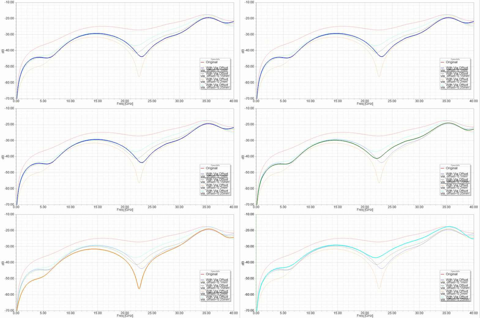
A more fundamental stage of signal integrity analysis often starts with analyzing and optimizing scattering parameters, which often unveils many of the SI design issues mentioned above. By running s-parameter extractions, SimuTech Group can provide touchstone or other model types that represent the extracted network for use in larger channel simulations or transient circuit analysis. Optimization of parameters such as insertion and return loss may often directly address isolated elements of the channel and substantially improve bandwidth and bit error rate (BER).

s-parameter-animation part 1
s-parameter animation part 2

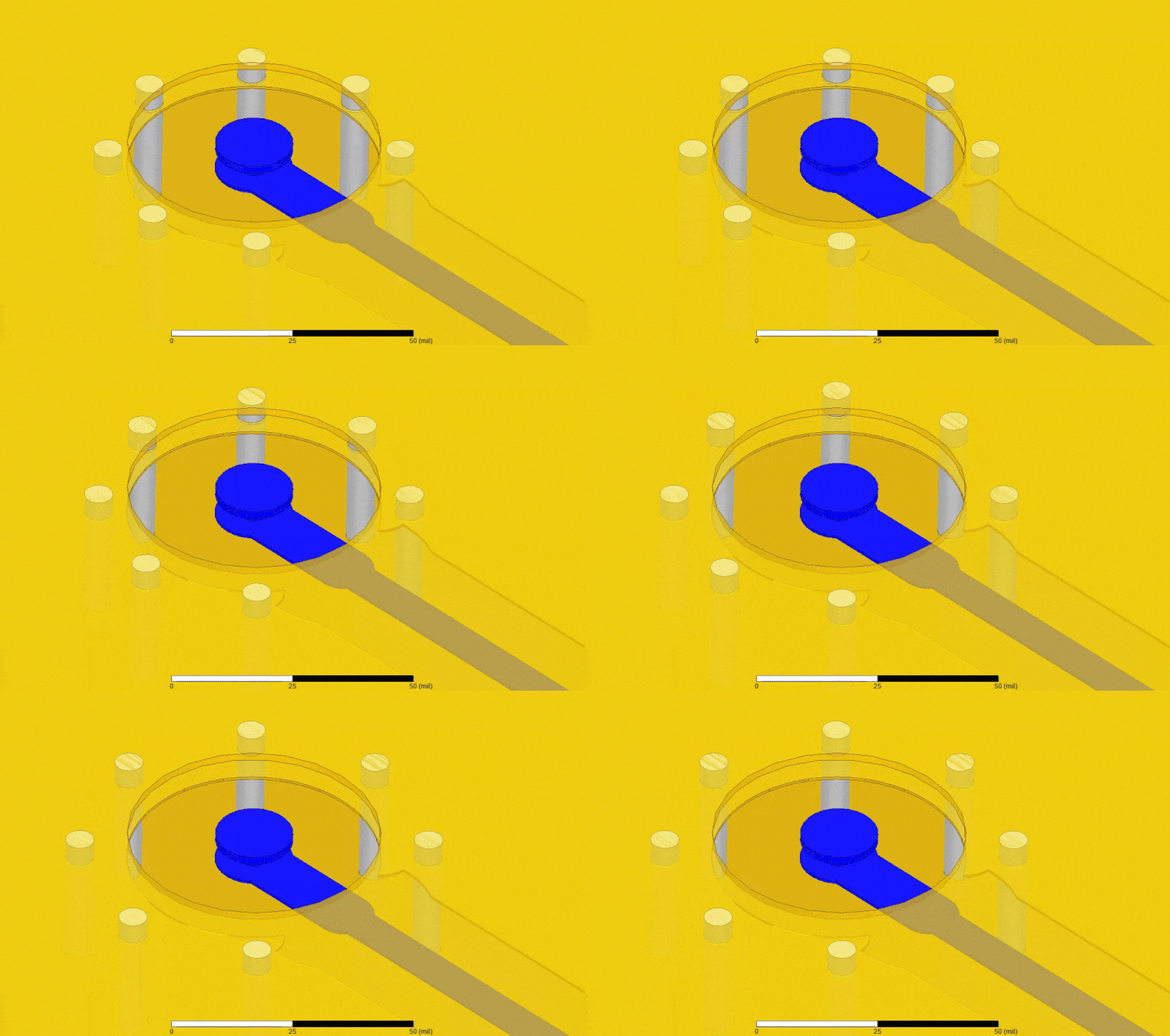
Parametric study to determine impact of via stitch spacing around SMA connector antipad

Time Domain Reflectometry Analysis

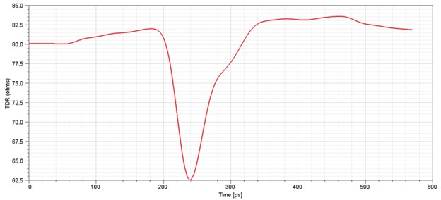
In order to determine the physical locations of imperfections that cause reflections and reduce channel bandwidth, SimuTech Group engineers perform TDR analysis to map impedance deviations over the length of the transmission line in order to make recommendations for each extracted channel component, such as board layout, connector, filter, etc.

tdr-analysis animation
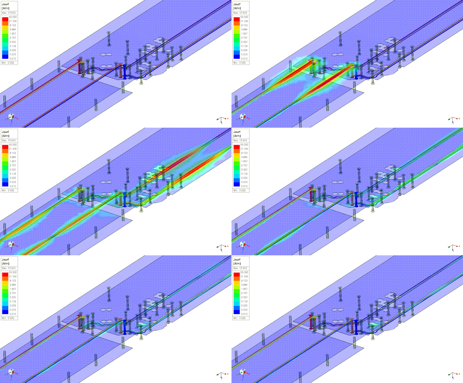
TDR analysis of microstrip differential pair routed across split reference plane through via transition

TDR analysis of a microstrip differential pair routed across a split reference plane through a via transition

Channel Modeling

While PCB layouts are common targets for modeling and loss analysis, a full channel model is often desired to capture all interface effects seen by a signal, such as connector, IC, and cable interfaces on board. When these components have model data, either as CAD files or encrypted HFSS components, SimuTech Group will explicitly analyze the full effects of these interfaces.

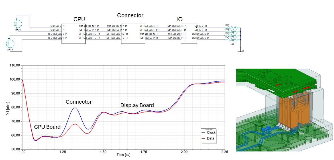
It is fairly common for vendors to only provide touchstone or SPICE models of their components. In this case, a channel model is built from various full-wave extractions of the transmission line and these component models cascaded in a single analysis, such as the mezzanine connector interface below demonstrating each element’s contribution to the TDR impedance profile.

signal-integrity-power-integrity-mezzanine-connector-interface

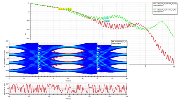
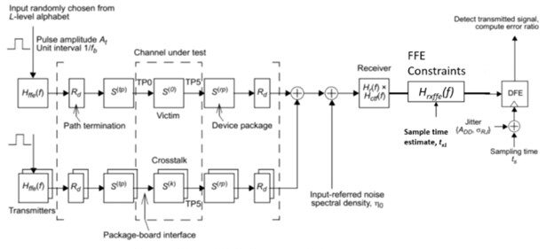
Once a channel model is assembled, driver and receiver models can be applied to produce projected time-domain output waveforms (at package pins or on-die) and directly relate the s-parameters and TDR results to an eye diagram.  Using IBIS-AMI models and solutions, SimuTech Group engineers can predict bit error rate (BER), eye opening with and without equalization, temperature and voltage-dependent corner cases, power supply deviation, clock jitter, and more.

sipi-IBIS-AMI-models

Power Integrity Analysis

Understanding both the low and high frequency implications of component placement and routing of a board’s power distribution network (PDN) can prove a complicated task, given the number of voltage regulators, current-drawing devices, decoupling capacitors, and high-speed lanes that reference this net. Using Ansys solvers such as SIwave and HFSS, SimuTech engineers perform several services related to power integrity, including the following:

  • DCIR Analysis: Determining DC voltage, current density, power loss distribution on power planes
  • Thermal Analysis: Solving temperature rise of layouts for DCIR drop on metallization and power draw from components, in addition to structural implications
  • PDN Extraction: Touchstone or SPICE equivalent modeling of PDN layout and components for time and frequency-domain circuit analysis
  • Decoupling Capacitor Optimization: Minimizing rail impedance and impact of AC transients on PDN by determining ideal capacitor values, locations, and routing
  • Resonance Analysis: Discovering resonant modes between power and ground planes and redesigning layout, interconnects, and decoupling capacitors to mitigate them
power-integrity-analysis

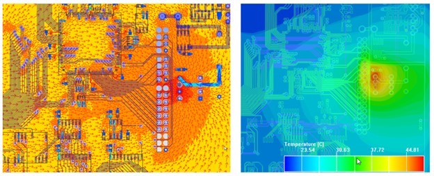
These facets of analysis can be divided between low and high frequency electromagnetic effects. Understanding DCIR drops and resulting temperature rise involves an understanding of low frequency effects of a board’s various sources and/or regulators, power draw of various components, and power plane routing and interconnects.

power-integrity-dc-service-current-density

DC surface current density (left) and resulting temperature profile (right) of power net routing near IC. Visit our Electronics Cooling and Thermal Analysis and PCB Design Analysis and Reliability pages for more information.

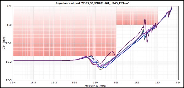
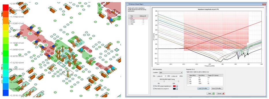
Much of the AC or high frequency interest in PDN design can be reduced to impedance measured looking into its various power pins, as pictured below.  An understanding of this metric elucidates the efficacy of power plane layout, decoupling capacitor choice and routing, and effect of filters in the vicinity of the pin of measurement.

impedance-by-port

Following extraction of an equivalent model of the PDN, time or frequency-domain circuit analysis can be performed to understand near and far field effects, predict AC ripple on device rails, and quantify the potential for simultaneous switching noise.

Additional SI/PI Analyses and Simulations

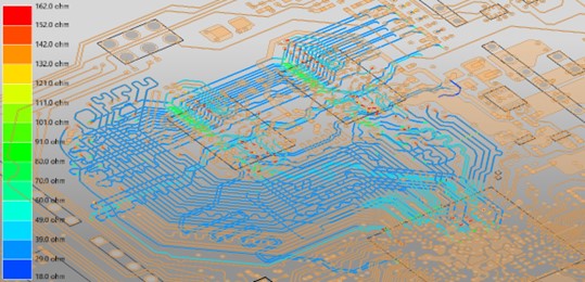
Characteristic impedance scan of address, data, clock, and strobe nets:

characteristic impedance scan

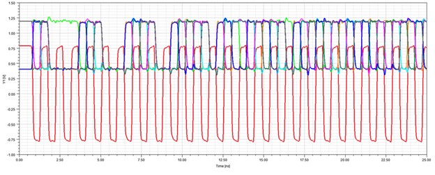
Transient analysis of output voltage waveforms at CPU receivers for read cycle:

transient analysis of output voltage

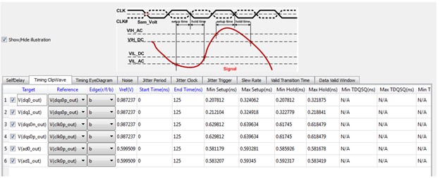
Virtual compliance report results for metrics such as self-delay, timing, eye width/height, noise, jitter, slew rate, valid data window, etc.:

virtual compliance report results part one
virtual compliance report results part two

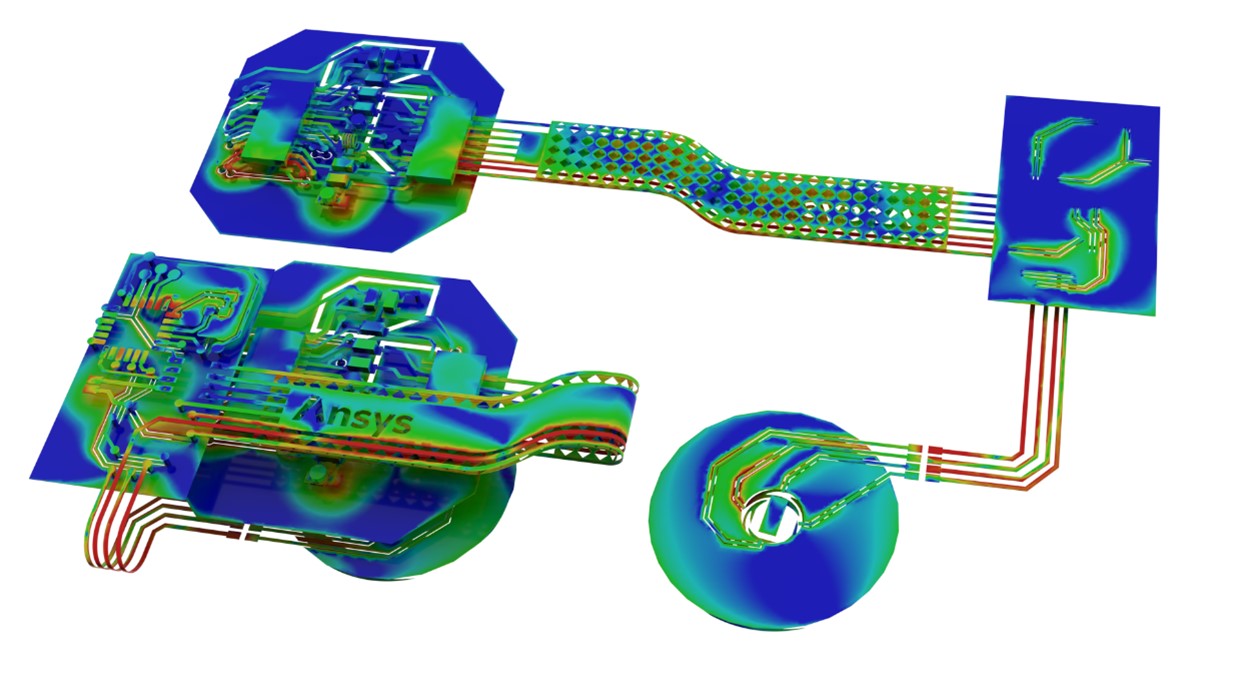
Rigid-flex PCB can be simulated in straight or flexed states to determine field-based effects on signal integrity performance.  Analysis of multizone stackups and impact of mesh ground planes on transmission line losses are studied.

rigid-flex PCB analysis
rigid-flex PCB analysis animation

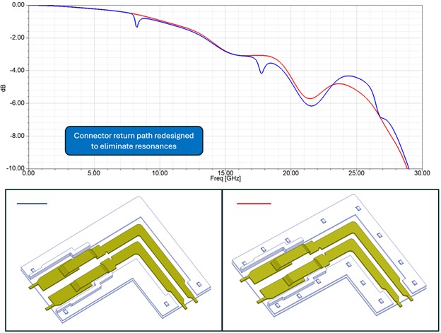
Insertion loss in backplane connector design indicates resonant behavior:

connector resonance analysis

Simulation in Ansys HFSS is used to remove the resonances and perform analysis on manufacturing tolerances to mitigate occurrence of additional dips in insertion loss.

resonance reduction simulation

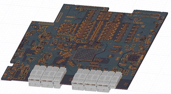
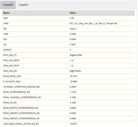
Modeling of large channels for high-speed transmission can help push supported bitrates higher. This often includes systems comprised of cascaded models that include PCB traces, connectors, cables, and ICs. On top of typical eye diagram and bathtub curve reporting, COM reports can be executed via Ansys automated workflows.

SERDES channel analysis circuit board graphic
SERDES com reports
COM reports graphical data
COM reports table data

With PDN impedance mask data known or derived from maximum allowable ripple specs on device rails, SimuTech Group engineers utilize vendor-specific capacitor models and optimizers to determine ideal component choice and placement. This type of analysis can not only pull down desired PDN impedance below specified limits but can also reduce the total capacitor count and number of different PNs by determining less effective component placement and redundancy.

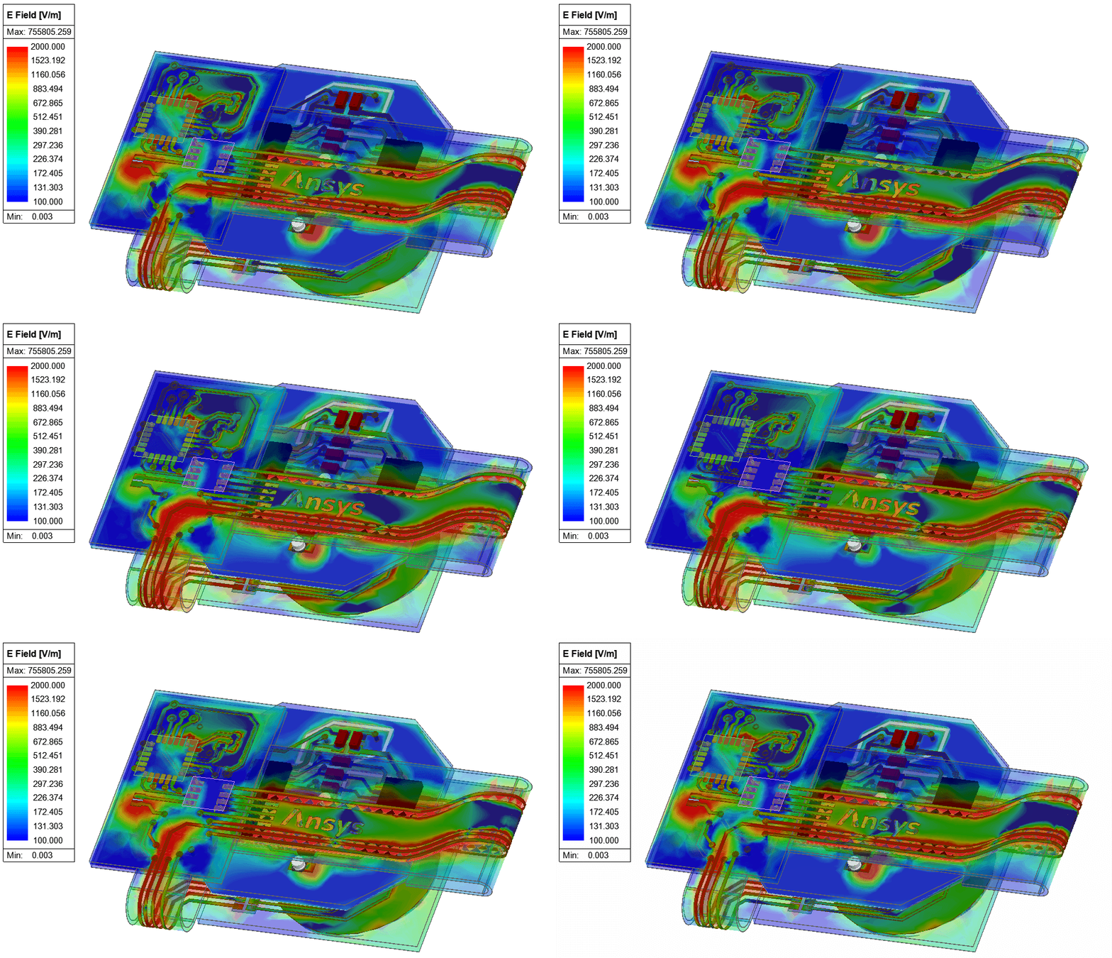
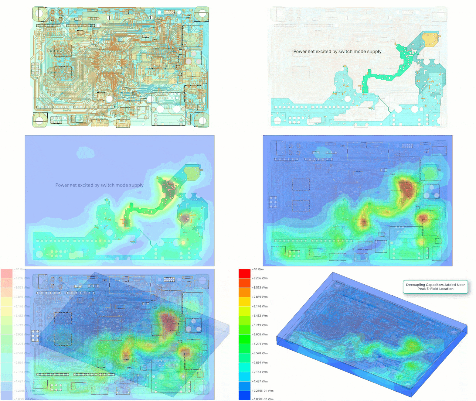
The example below demonstrates optimization of decoupling capacitors on a power plane excited by a switch-mode power supply. As the input impedance of the rail is reduced over frequency, near field emissions are shown to drop.

optimization of decoupling capacitors
optimization-of-decoupling-capacitors-on-a-power-plane

Achieve Optimal Performance with SimuTech Group’s Consulting Services

Maximizing the performance of your electronic systems requires addressing multiple factors, from signal integrity to power integrity, thermal management, and beyond. SimuTech Group offers comprehensive electromagnetic consulting services, utilizing advanced Ansys simulation tools and deep industry expertise to help you achieve highly optimized designs and  the most reliable outcomes.

Looking to improve your designs? Contact SimuTech Group today for a consultation and see how our solutions can support your next project.

We’re Here to Help

Our team of experienced engineers can assist you at any step of your process.