How to Create an Elastic Support w/ Normal and Tangential Stiffness in Ansys Workbench
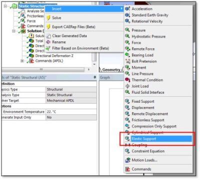
Ansys Mechanical Workbench has an object for an elastic foundation that provides an elastic foundation stiffness and acts in a direction normal to selected faces on a body. It does not provide any stiffness that acts in a direction that is tangent to faces. An elastic foundation that will act in both normal and tangential directions on selected faces can be created via an APDL Commands Object that is inserted into the Outline of a model. The creation of such a support is reviewed in this article.
Creating Elastic Support with Normal and Tangential Stiffness
Workbench has an Elastic Support that acts on faces of 3D models. It offers stiffness per unit area, but this stiffness acts only in a direction that is normal to faces:
Users occasionally want an elastic support on a face that has stiffnesses that act in both normal and tangential directions to the face. Such a support can be created with an Ansys APDL Commands Object inserted into the Outline of the Workbench Mechanical model.
A Named Selection is used to indicate the face or faces of interest. The APDL commands coat selected solid faces with CONTA174 elements using the ESURF command, make a copy of the nodes of the CONTA174 elements with the NGEN command, and use those nodes to make copies of CONTA174 elements that become TARGE170 elements with the same morphology, using the EGEN command.
It constrains the nodes of the TARGE170 elements in all directions, and flips the TARGE170 elements to face the CONTA174 elements using the ENSYM command.
Bonded Contact Settings | Elastic Support for Selected Faces
The contact pair is set to use Bonded Always contact. Manual inputs of absolute values for normal stiffness FKN, and tangential stiffness FKT are assigned to the CONTA174 elements. This provides an elastic support to the selected faces. The FKN and FKT values are entered as stiffness per unit area, and can be independent of each other. In cases where only a normal stiffness is wanted, the provided Elastic Support of Workbench Mechanical can be used.
If the Commands Object is used, it must be provided with three Input Arguments:
ARG1 = Normal contact stiffness in units of (Force/Length/Area)
ARG2 = Tangent contact stiffness in units of (Force/Length/Area)
ARG3 = Pinball Radius for the contact pair (Length units)
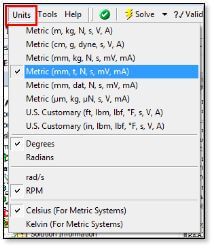
It is necessary that the three Input Arguments employ the units that will be used during the SOLVE of the model. This choice of units can be set with the Units entry of the menu of the Workbench window:
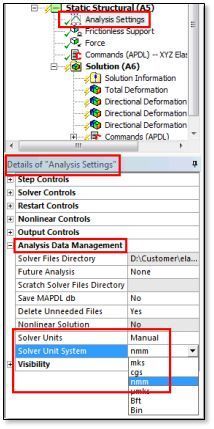
It can also (or alternatively) be controlled in the Details of Ansys Settings for the environment of interest:
If Normal stiffness is entered and Tangent stiffness is not set or is zero, Tangent Stiffness is set to Normal Stiffness (no warning is issued). Normal and Tangent Stiffness can be set to different nonzero values. The pinball radius should be significantly larger than the amount that the contact surface is expected to move during the analysis, and must be entered with a positive value. It too must be entered in the correct dimension units of the SOLVE.
The Bonded Always contact pair gives the elastic support action, since absolute values for contact stiffness are provided for both FKN and FKT, and the target elements are fully constrained. Note that the contact pair cannot be reviewed by the tools that are built into Workbench Mechanical—it is created at SOLVE time only. This approach has worked in simple linear tests with high-order and low-order solid elements. The technique may not be suitable in Large Displacement analysis if there are substantial movements at this elastic support.
Creating Elastic Support | Application Commands
The following is a listing of the APDL Commands Object. Note that the Named Selection “Elastic Here” is used to indicate the face or faces that are to have the elastic support applied:
! Commands inserted into this file will be executed just prior to the Ansys SOLVE command.
! These commands may supersede command settings set by Workbench.
! Active UNIT system in Workbench when this object was created: Metric (mm, t, N, s, mV, mA)
! Generate an elastic foundation in normal and both tangent directions
! on Named Selection “Elastic_Here”, a set of nodes on face(s).
!
! These commands have been tested on a 3D solid model only.
!
! ARG1 is the NORMAL stiffness (Force per Unit Length per Unit Area)
! ARG2 is TANGENTIAL stiffness (Force per Unit Length per Unit Area)
! ARG3 is Pinball Radius, in solver units
! ARG1 & ARG2 must be in the solver units!
! If ARG2 is blank or zero, it is set to ARG1
! ARG1 must be non-zero.
! If ARG3 is zero, then zero will be used, which should activate default
!
*if,ARG1,LE,0,then
*MSG,ERROR
ARG1 for Normal Stiffness on XYZ Elastic Foundation must be positive
/EOF
*return,-1
*endif
!
*if,ARG2,LE,0,then
ARG2=ARG1
/COM,######## ARG2 was made equal to ARG1 ########
*endif
fini
!
/prep7
!
*get,nodemax,NODE,,NUM,MAX ! highest node number in model
!
cmsel,s,Elastic_Here ! nodes of the component “Elastic_Here”
esln ! select contacting elements
!
! undselect surface effect, contact, MPC and beam elements
esel,u,ename,,151,154
esel,u,ename,,169,180
esel,u,ename,,188,189
*get,maxtype,ETYP,,NUM,MAX ! highest element type
*get, maxmat,MAT,,NUM,MAX ! highest material type
*get,maxreal,RCON,,NUM,MAX ! highest real constant
! Set maxtype, maxmat and maxreal to the highest value of all three
*if,maxtype,gt,maxmat,then
maxmat=maxtype
*else
maxtype=maxmat
*endif
*if,maxreal,gt,maxtype,then
maxtype=maxreal
maxmat=maxreal
*else
maxreal=maxtype
*endif
! Create required element types and real constant
ET,maxtype+1,CONTA174,,1,,0,3 ! Pure Penalty contact algorithm (stiffness)
KEYOPT,maxtype+1,9,1 ! Exclude initial geometrical penetration or gap and offset
KEYOPT,maxtype+1,12,5 ! Bonded Always
ET,maxtype+2,TARGE170,,1 ! Constraints by user
R,maxreal+1,0,0,-ARG1,,,-abs(ARG3) ! FKN Absolute Number, ARG3=Absolute Pinball Radius
RMODIF,maxreal+1,12,-ARG2 ! FKT as Absolute Number
!
TYPE,maxtype+1 ! CONTA174 elements
REAL,maxreal+1
MAT,maxmat+1
ESURF ! Mesh CONTA174 over underlying element faces
!
*get,current_nodemin,node,,num,min
!
esln,r,1 ! Select only these CONTA174 elements
esel,r,ename,,174 ! Ensure no other elements
esel,r,real,,maxreal+1
!
! Make a copy of the currently selected nodes
NGEN,2,(nodemax-current_nodemin)+1,ALL,,,0,0,0 ! Copy of nodes at same location
EGEN,2,(nodemax-current_nodemin)+1,ALL,,,0,1,0 ! Copy elements, increment TYPE by 1
!
esel,r,type,,maxtype+2 ! Select these new TARGE170 elements
ENSYM,0,,0,ALL ! Reverse TARGE170 elements to face contacts
nsle ! Select nodes on these target elements
d,all,all ! Constrain all nodes on target elements
!
allsel
! Continue with the analysis
fini
/solu
!
Note that CONTA174 elements have been employed. In testing these were found to work when low-order solid elements were used in the model, so the method appears to be applicable to both high-order and low-order solid elements.
Conclusions | Create Elastic Support in Ansys Mechanical Workbench
An elastic support that acts in both normal and tangential directions can be created in Workbench, using an APDL Commands Object that builds a CONTA174 to TARGE170 contact pair set to Bonded Always and is provided with FTN and FLT values for normal and tangential stiffness values.
Since the contact pair is generated at SOLVE time, the Contact Tool of Workbench is not applicable.
Users must enter normal and tangential stiffness values as Input Arguments to the APDL Commands Object, as well as a Pinball Radius value that is larger than resulting movements at the elastic support. Units for these three arguments must be those of the SOLVE process for the model.
Contact for Additional Ansys Mechanical and/or Elastic Creation Support
Finally, we hope that you can make productive use of our Elastic Creation/Support article, and varying supportive computations for your Ansys Mechanical models. For more information, or to request engineering expertise for a particular use-case scenario surrounding creation of elastic support with normal and/or tangential stiffness, please contact us here.