Introduction
Sometimes you don’t get a second chance.
For those working in harsh marine environments, safety is paramount. A bad day at work can quite literally mean not making it home.
Motivated by the inherent dangers of working in harsh environments, Enginuity’s mechanical engineering team embarked upon building a safe, secure and easily deployable marine launch/recovery and mooring device.
The result was SEALift™ / SEAStab™ collectively known as SEALine ™.
The Challenge
The development of reliable marine asset launch and retrieval systems and mooring systems involve complex engineering challenges. Varying use cases, and challenges with vibration and corrosion are considerations inherent to the design of these systems and these factors can complicate a system that must inherently remain simple to deploy and operate.
Marine LAR and mooring systems also require adherence to comprehensive certification frameworks. And as SEALine™ would find itself in both commercial and military applications, stringent regulatory approvals were to be met. Satisfying the requirements of DNV, LR and ABS can be costly and drive schedule.
Key Design Requirements
While tethering something to the ocean floor may seem like a simple ask, there are considerable forces that inform design from prototype to deployment. Modern simulation techniques conducted during the preliminary and detailed design phases can effectively help in verifying suitability.
Key requirements:
- Must function reliably in harsh marine environments
- Zero-tolerance for failure under extreme loading conditions
- Capability to resist cyclic loads and vibrations
- Need for rapid, repeatable, secure connections and disconnections
- Binary connection (no false lifts)
Simulation Approach
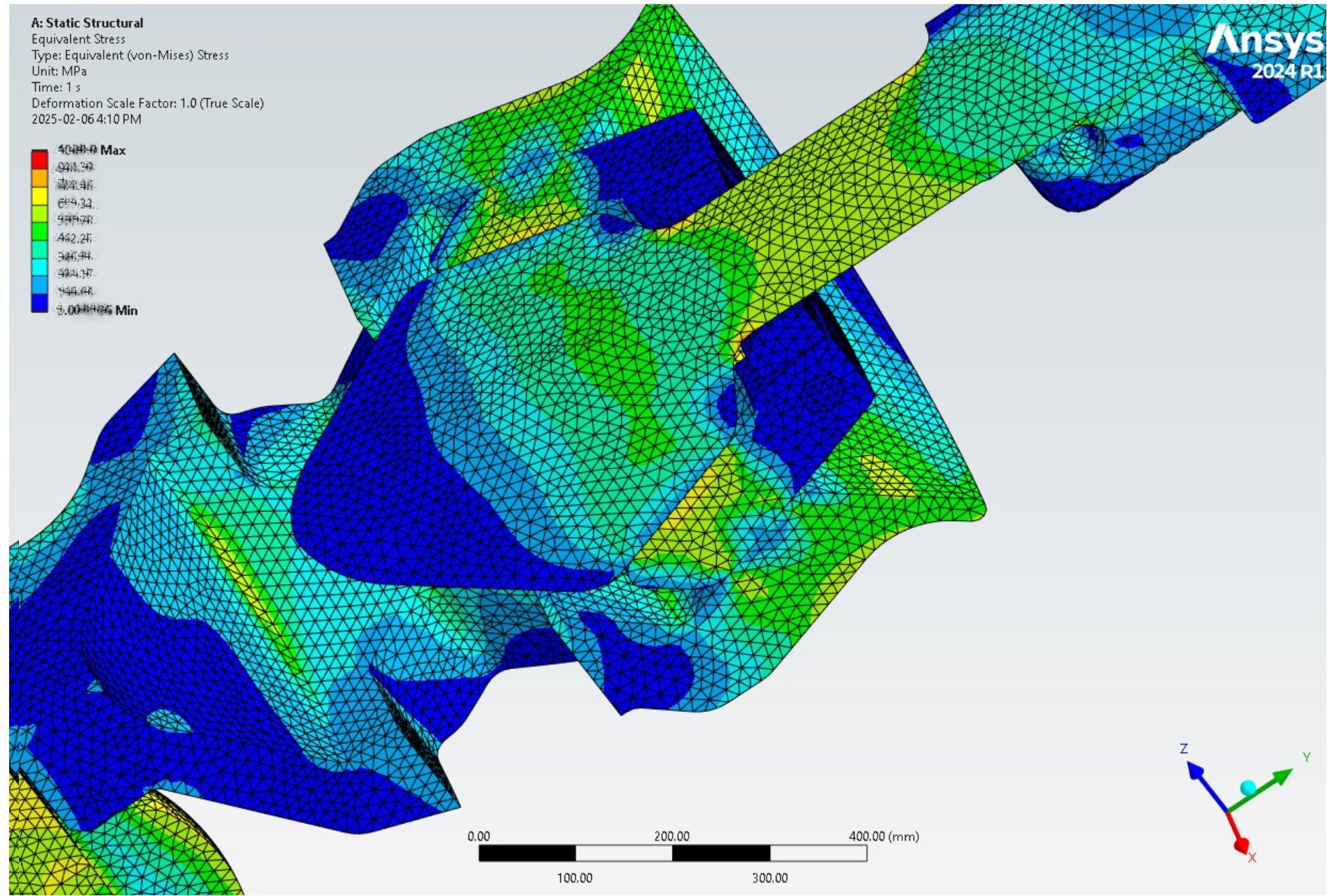
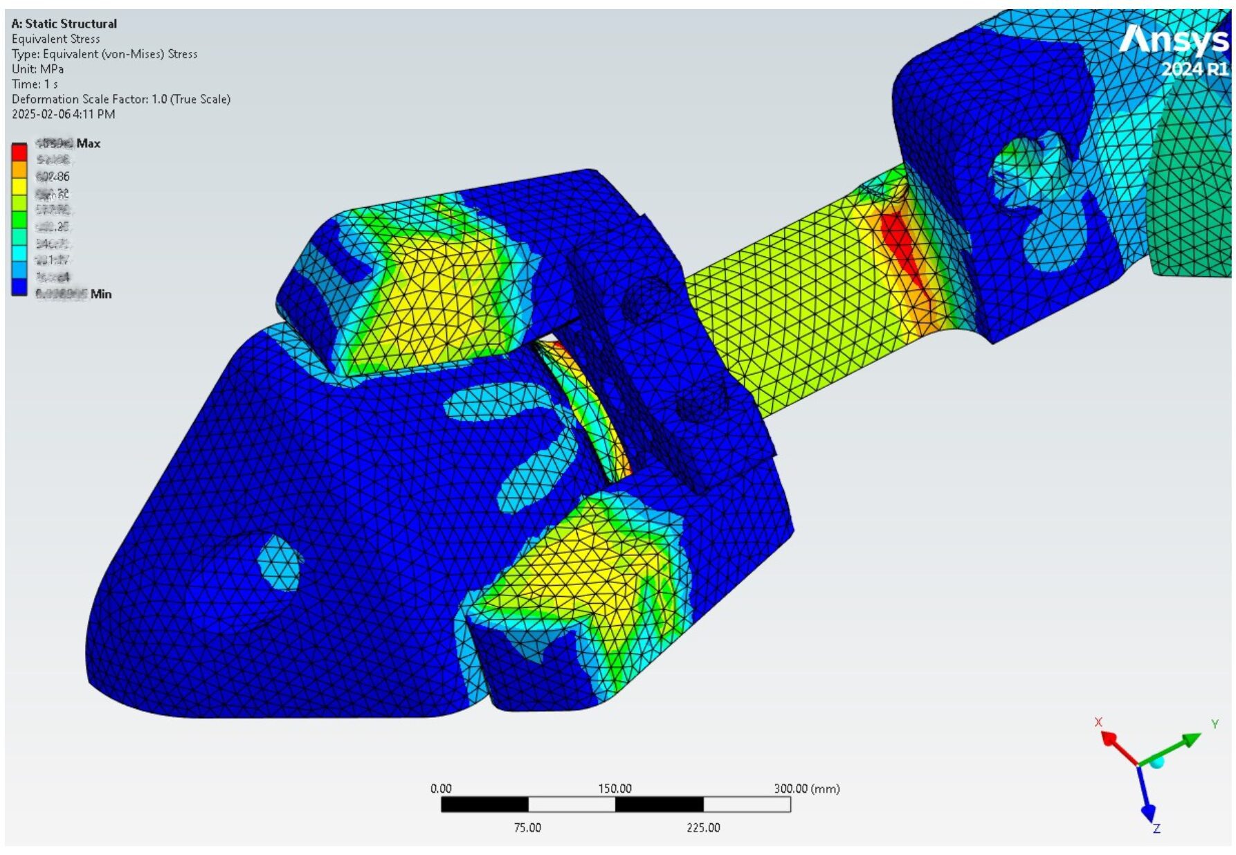
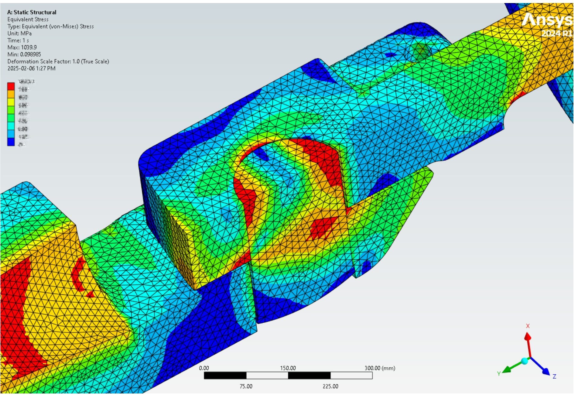
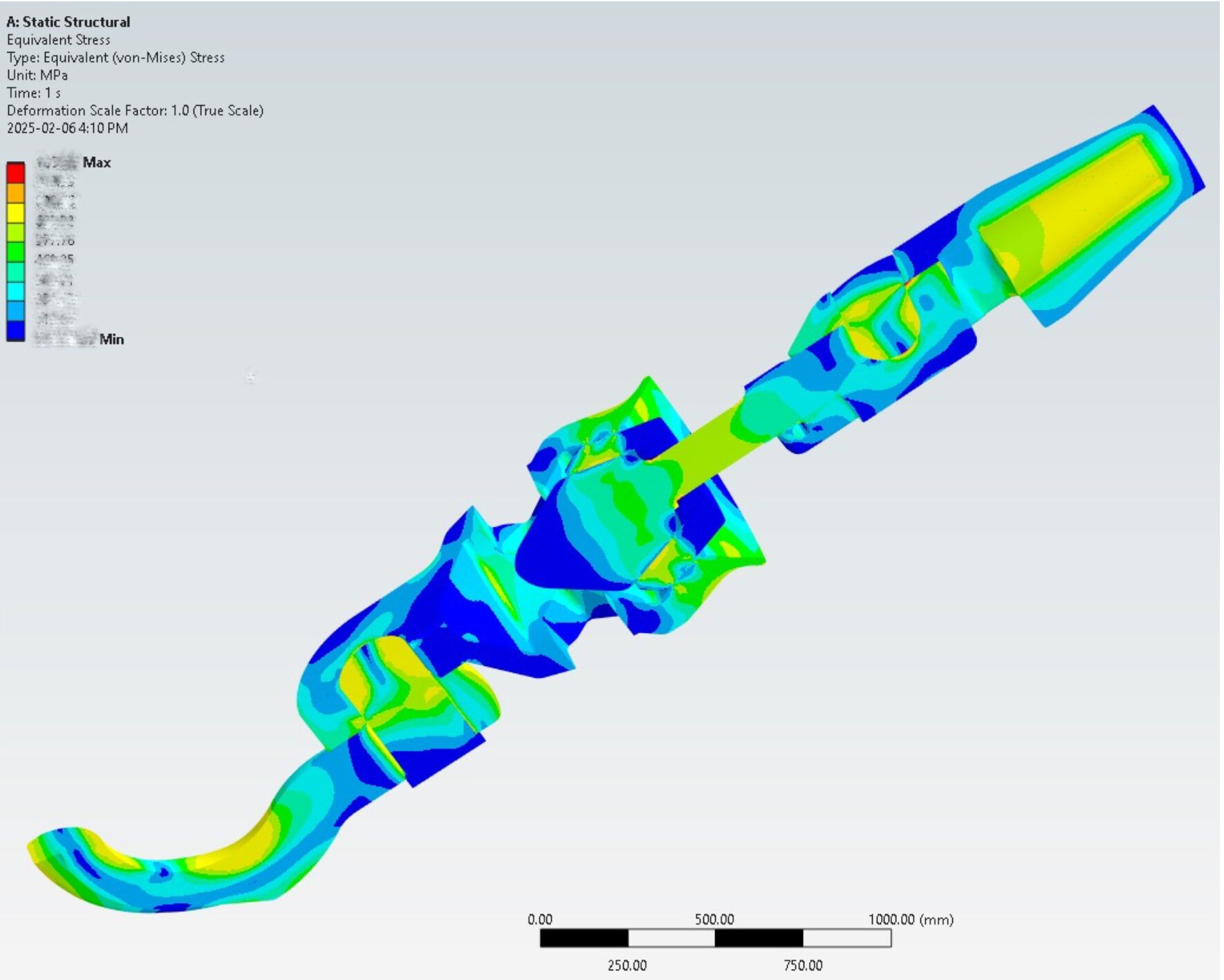
The SeaLine product is inherently mechanically simple in that load is transferred at the interfaces between standard clevis or pad eye arrangements, and the quick connect consists of a tapered cone and locking wedges arranged at the end of a round shaft. However, the Ansys Simulation approach allows a greater depth of understanding with respect to:
- Contact pressure distribution as a function of load
- Non-linear analysis of the hertzian tapered cone interaction in the wedge mechanism
- Characterization of geometric hotspots and transitions
- Large deformation and plasticity behaviour near specified breaking load
- Stress sensitivity data for calculation of Mean Time Between Failure for fatigue limit state
- Design validation and verification through simulation and physical testing
Beyond Standard Analysis
The robust contact algorithm within Ansys allows engineers to quickly characterize hertzian frictional contact behaviour in “large” finite element models. The robustness of the implicit solver in obtaining convergence in large contact models with highly distorted geometry in the plastic regime is second to none.
Technical Support Integration
To maintain the original design, minimise the potential to be “over-engineered”, and account for all conditions mentioned above, an array of Ansys simulation tools were required. Support from SimuTech Group, the largest certified Ansys partner in North America, and its team of experienced engineers contributed to successful modelling and analysis.
SimuTech Group’s engineers, understanding both the theoretical and practical aspects of applying simulation to real-world marine problems, were integral partners. Their support included:
- Advanced solver capability
- Troubleshooting convergence issues
- Guidance on optimal modeling approaches
This access to a host of simulation tools, in conjunction with real-world prototyping and testing, proved invaluable to the timely development of the product. Furthermore, the classification societies found the data from the Ansys tools essential for diligent certification. The SEALift was now ready for use.
Conclusion
Today, thanks to comprehensive simulation, rigorous testing and validation, SEALift is used globally by operators in the energy, defence, and commercial marine sectors. These operators can be certain that their marine assets can be safely moored, deployed and retrieved. And, that all personnel will make it home to harbour, safely, on time and on budget.