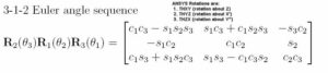
Workbench Convention Adopted in Ansys for Rotations
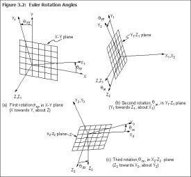
In a variety of situations when using Ansys software, whether through the Mechanical APDL interface, or the Workbench the convention adopted in Ansys for rotations, such as the rotational degrees of freedom of a node or of a coordinate system, is the 3-1-2 “Euler Angle” sequence. In this sequence, a first rotation is taken about the original Z axis, a second rotation is taken about the X′ axis that results from the first rotation, and a third rotation is taken about the Y″ axis that results from the second rotation. Using updated axes for the second and third rotations is called “intrinsic rotation”. Nodal degree of freedom rotations are expressed in radians in Ansys. Rotations of coordinate systems are expressed in degrees.
The term R3 is used to refer to a rotation about a Z axis, R1 refers to a rotation about an X axis, and R2 refers to rotation about a Y axis. The 3-1-2 rotation sequence means rotations about Z, then X′, then Y″.
The right hand rule is used for rotations in Ansys. In the following rotation matrix figure:
θ1 is the size of the first rotation about the original Z axis (called THXY in ANSYS)
θ2 is the size of the second rotation about the updated X′ axis (called THYZ in ANSYS)
θ3 is the size of the third rotation about the recently updated Y″ axis (called THZX in ANSYS)
Using the following notation:
c1 = cos(θ1) s1 = sin(θ1)
c2 = cos(θ2) s2 = sin(θ2)
c3 = cos(θ3) s3 = sin(θ3)
R3 = first rotationθ 1 about the original Z axis
R1 = second rotation θ2 about the new X axis (X′) that results from rotation R3
R2 = third rotation θ3 about the newest Y axis (Y″) that results from rotation R1
A rotation matrix can be created for transformations via these three rotations:
Users will recall that rotations do no commute.
Extra Information | Ansys Rotations
Note that a variety of 3-rotation sequences could have been chosen when creating Ansys, which chooses to use the 3-1-2 convention.
Various disciplines (vehicle engineering, flight dynamics, robotics, computer graphics, and others) and software packages choose from several 3-rotation angle possibilities. Some authors distinguish Euler angles, in which the (updated) first axis used is repeated in the third rotation, from Tait-Bryan angles, in which each axis is used once only (an example is roll-pitch-yaw).
Euler angles
1-2-1 1-3-1 2-1-2 2-3-2 3-1-3 3-2-3
Tait-Bryan angles
1-2-3 1-3-2 2-1-3 2-3-1 3-1-2 3-2-1
The convention chosen can depend on where the singularity of the inverse rotation is located, and whether it is inconvenient for the discipline in which the convention is adopted. If there must not be a singularity in an inverse rotation, a common choice is to use Euler Parameters (Quaternions), a 4 term rotation convention, in which the 4 terms include a non independent parameter that constrains the other 3 parameters. In the Ansys help system there is brief mention of Ansys using quaternions internally.
Ansys Mechanical | Euler Rotation Angles
An image of the Euler Rotation Angles is given in the Mechanical APDL Modeling and Meshing Guide:
Sample Question | Rotations given Boundary Conditions for Symmetry
Question:
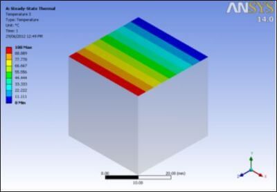
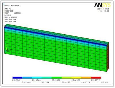
- Let us assume we want to apply some boundary conditions for symmetry, how do we do it for above geometry, given it is bi-symmetric. One could put the plane at which they are symmetric displacement to zero, but what about the rotations? How is this accounted for, and completed?
Answer:
There are three methods to have an accurate symmetry BC. Choose one, don’t do more that one at a time.
- Use DesignModeler ► Insert Symmetry. You have to pick a plane. It will automatically create the proper BC in Mechanical, behind the scenes.
- Model branch in Mechanical ► Insert Symmetry Region. Pick a face or edge. Make sure the Axis direction is correctly specified. In earlier releases, it would default to the X axis even if the symmetry plane was parallel to the XY plane and the proper value for normal direction was the Z axis. This was a source of error. The Ansys 2022 R1 release sets the direction properly automatically. Once you have done that, the proper BC are set for you behind the scenes.
- Insert BCs explicitly into Static Structural branch ►
- A) For solid elements on the symmetry plane, set the displacement to 0 on component normal to the plane, leaving the other two displacements free.
- B) For shell or beam elements, in addition to the displacement set in a), you must also insert Fixed Rotation for the two axes that lie in the symmetry plane.
Method 3 is precisely what the two preceding methods are doing behind the scene.
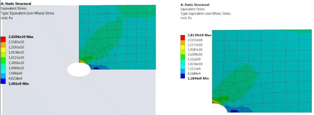
Using a Mesh Control to force smaller elements on the edge of the hole is also recommended. Second, if the anticipated stress is large, adjust the load orders accordingly.
Contact for Additional Ansys Mechanical Support
Finally, we hope that you can make productive use of our Ansys Rotations tips & tricks, and the various computational pathways to achieve your ideal Mechanical models. For more information, or to request engineering expertise for a particular use-case scenario surrounding solid element symmetry, Euler angles, Tai-Bryan angles, or general inquires on Ansys Rotational features, please contact us here.