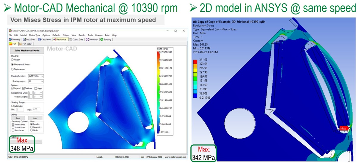
Ansys facilitates comprehensive system integration by seamlessly transferring data from design through analysis and validation to final verification stages. This process mimics human-like testing, ensuring thorough system simulation within a unified workflow.
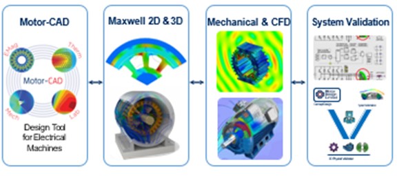
Given the conflicting requirements of various physics processes in motor design, consolidating all analyses into a single platform is essential. The platform’s primary objective is to evaluate potential designs based on their performance across electromagnetic (EM), structural, thermal, and noise, vibration, and harshness (NVH) analyses.
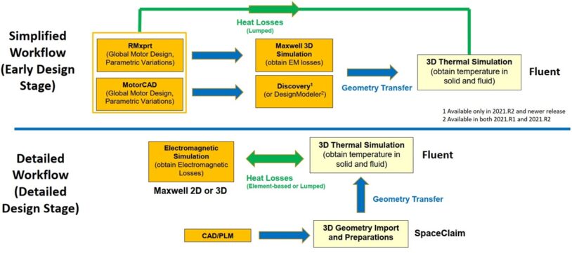
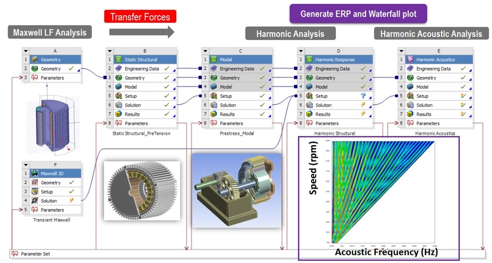
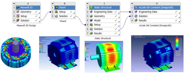
This integrated approach enables the identification of an optimal design that meets all performance targets across different physics domains. Within Ansys Workbench, a unified coupling workflow is established to facilitate seamless data exchange between analyses.
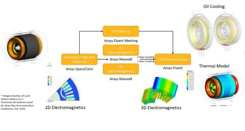
Following electromagnetic (EM) analysis, loss data is transferred to Ansys Fluent for computational fluid dynamics (CFD) analysis, specifically evaluating cooling through a water-jacket in the motor housing. This analysis provides surface temperature insights crucial for subsequent analyses.
A two-way feedback connection, illustrated in the workflow, links EM and CFD analyses, enabling temperature effects on various quantities to be iteratively refined. Temperature data is further integrated into structural and NVH modules, enhancing accuracy in stress calculations and acoustic noise predictions.