Air Duct Noise Silencer | HVAC Noise Propagation
When building an HVAC system, people must often consider the noise that is generated by the flow in the ducts. To help prevent from too much noise propagation, silencers or mufflers need to be designed. This design is critical, as the result is often a trade-off between various criteria (geometry, pressure loss in the flow, transmission loss…)
Ansys R18 has new out-of-the box capabilities to help engineers run multiple simulations to understand the acoustic behavior of silencers.
This article showcases the process of setting up an acoustic harmonic analysis by giving you tips and tricks on how to proceed to get quick and accurate results.
Geometry Preparation
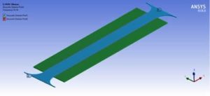
At first sight, geometry may appear complex, since both fluid and structural parts must be considered:
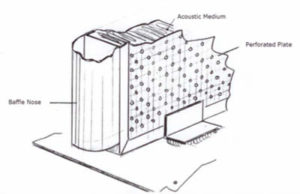
Thus, the FE model will have:
- One body for the duct channel (air)
- One body for the plate
- One body for the porous medium
As it is highly recommended to avoid contact regions between parts, the geometry will be one single multibody part.
Instead of representing the perforated plate as is, concerning HVAC noise propagation, Ansys Mechanical enables us to use perforated plate models. In addition, removing the analogous the holes which greatly simplifies both the geometry and the analysis. As far as HVAC meshing is concerned, this will alleviate engineers from an otherwise convoluted (nightmarish) task.
Even though cyclic symmetry is not an option, as its current formulation only takes structural DOFs into account (pressure DOFs will be missing in the constraint equations), we can also take advantage of the linear periodicity in the horizontal plane by modeling only one channel.
Indirectly Performing 2D Acoustic Analysis in Ansys Mechanical
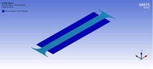
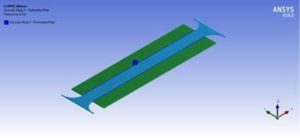
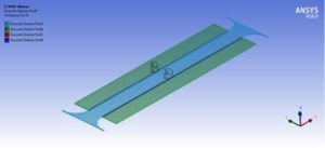
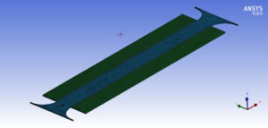
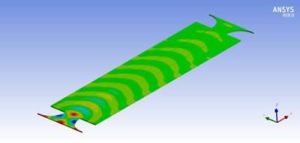
Since we can neglect phenomena in the vertical direction, it is possible to downsize even more the model. Mechanical does not permit 2D acoustic analysis, but we can indeed use what CFD people call 2D1/2 by taking a thin slice of the whole model with one single layer of elements in the vertical direction. Thus, the geometry will look like the following one:
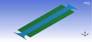
No specific boundary conditions will be needed on the horizontal boundaries as the absence of condition is equivalent to have no reflection on the boundaries.
If iterations are to be made on the design, a good way to avoid repeating tasks in the pre-processing phase when design changes is to define named selections on:
- Acoustic bodies
- Inlet, outlet
- Acoustic ports
Material Property
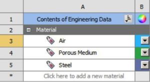
Acoustic bodies will be defined in Mechanical, so there is no real need of defining material properties in the Engineering Data. However, it is a good practice to duplicate the default material – which more than often is Structural Steel – and to create 3 materials from the library:
- Air
- Porous Medium
- Perforated Plate – which is often made in steel as well
Change the color of those materials, and set the Display Style to be by ‘material’ in Mechanical. You will then have a better visualization of the model.
Boundary Conditions
Acoustic Bodies
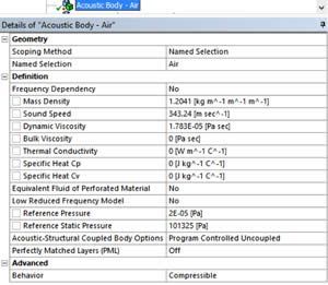
To use acoustic elements (FLUID30. FLUID220 or FLUID221), acoustic bodies need to be defined on:
- The duct channel: just specify the air acoustic properties – which are the default ones
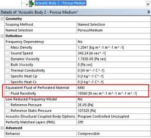
- The porous medium: here the user has to specify the properties of the equivalent fluid of the porous material. Depending on the material properties that are provided, different physical models can be used:
- Johnson-Champoux-Allard (JCA):
- Fluid Resistivity σ,
- Porosity φ,
- Tortuosity α∞,
- Viscous Characteristic Length Λ,
- Thermal Characteristic Length Λ’
- Delany-Bazley (DLB):
- Fluid Resistivity σ
- Used when 0.01 < F/σ <1.00
- Miki (MIKI):
- Fluid Resistivity σ
- Used when 0.01 < F/σ <0.01
- Complex Impedance and Propagating Constant (ZPRO):
- Resistance Rs,
- Reactance Xs,
- Attenuation Constant α,
- Phase Constant β
- Complex Density and Velocity (CDV):
- Complex Effective Density
- Velocity
- Johnson-Champoux-Allard (JCA):
In the current example, the MIKI model was chosen:
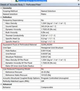
- The perforated plate: the plate is simplified by using a 2×2 transfer admittance matrix to trim the complicated perforated structure, instead of meshing it with its holes. Depending on the hole pattern, 3 models are available for the transfer matrix:
- Hexagonal grid plate (HGYM)
- Square grid plate (SGYM)
- General transfer admittance matrix (YMAT)
For the first two models of grid plates, the following parameters have to be defined:
- Holes Radius
- Grid Period
- Plate Thickness
- For cylindrical structures, ratio of inner and outer structure (value of 1 can be taken for flat plates)
If those parameters match the actual design, results will be the same as the case where the actual holes are considered.
Acoustic Exterior Ports
Ports are used to locate specific acoustic regions to:
- Define Transfer Admittance Matrix between two ports
- Calculate Sound Power Results (input power for one port or transmission loss between two ports)
Therefore, 6 acoustic exterior ports will need to be defined:
- At the inlet and the outlet for transmission loss calculation (Port 1 and 2). It is advised to use Port Number 1 and 2 for Power Result Plots.
- At the vertical boundaries of the two perforated plates to define the transfer admittance matrix
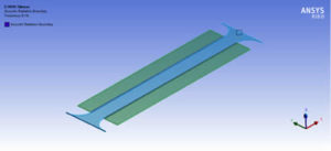
Radiation Boundary
To avoid waves to be reflected at the inlet and the outlet, an acoustic radiation boundary is defined at the locations shown on the following figure. This condition is called the Robin condition.
Normal Surface Velocity | Sound Propagation
As an excitation, a normal velocity can be applied on the inlet to simulate the sound generated by the vibration of a surface.
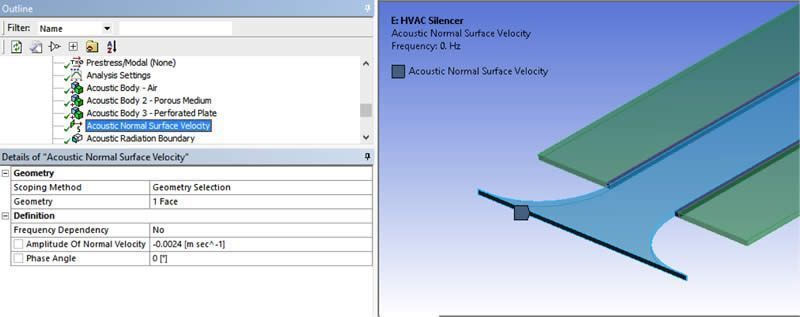
Usually, this kind of analysis is made to get the transmission loss result (see results), which is a rate of incident of energy versus the transmitted one. The magnitude of the excitation at the inlet is thus not critical. It is however important to understand that this value is not the value of the flow speed.
Meshing
Meshing is critical in HVAC noise propagation and/or general acoustic analysis’, especially as far as the element size is concerned.
The element size must be tightly related to the wavelength:
To capture the sound propagation with accuracy, here are the rules to be followed:
- If linear elements (no mid-side nodes) are used, at least 12 elements per wavelength are needed
- If quadratic elements are used, only 6 elements per wavelength are required
Note for the meshing of the perforated plates: Trim element for transfer admittance matrix is only available for hexahedral and prism elements. For hexahedral elements, only a pair of opposite element faces can be defined as the ports. In case of prism elements, only two triangular element faces are used for the ports. A pair of ports of the 2×2 transfer admittance matrix must be defined in the same element. There is no limitation on the trim element mesh size between two ports.
Pre-Acoustic Simulation | Ansys Workbench Analysis Settings
A few steps are required:
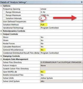
- The frequency range needs to be defined
- The ‘Full Method’ must be specified.
- The MAPDL database needs to be saved
- The ‘General Miscellaneous’ results must be calculated
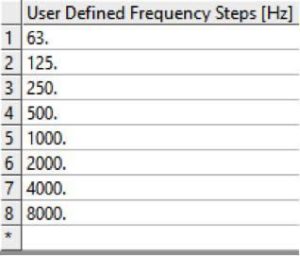
Several options are possible to define the analysis frequency range. The most convenient way may be to use the User Defined Frequency options and to specify the frequencies at which data are usually given for acoustic absorbers i.e. the center frequencies of octave bands ([63 Hz, 125 Hz, 250 Hz, 500 Hz, 1000 Hz, 2000 Hz, 4000 Hz, 8000 Hz])
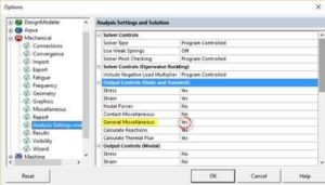
The last two points can be set for all analysis in the Mechanical options:
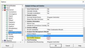
Ansys Workbench Results | Acoustic Pressure Analysis
The acoustic pressure at each analysis frequency can be plotted and animated.
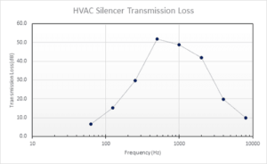
The most common requested result is the transmission loss curve. The Transmission Loss (TL in dB) is the rate of incident sound power which is transmitted through the system:
To define this result, simply ask for an ‘Acoustic Power Result Plot’ using the acoustic exterior ports 1 and 2 which are associated to inlet and outlet (respectively) defined in the boundary conditions.
![]()
Or in a logarithmic scale (as it is usually provided):
Conclusion | HVAC Noise Propagation & Acoustic Simulation
The solution took less than one minute to solve the HVAC Noise Propagation with 2 cores. It would be very easy and fast to optimize the design of a silencer using DesignXplorer. One would simply need to define parameters such as geometrical dimensions and/or material properties like porous medium resistivity, maximum transmission loss, etc.
Adopting simulation driven product development would be beneficial in this case since evaluating multiple virtual prototypes would be much better than the classical process of making real prototypes and testing them.
Contact for Additional Ansys Mechanical and/or HVAC Propagation Analysis
Finally, we hope that you can make productive use of the HVAC Noise Propagation & Acoustic Simulation studies and resources to optimize your Ansys Mechanical models. For more information, or to request engineering expertise for a particular use-case scenario surrounding acoustic simulations, please contact us here.