How To Export a Deformed Geometry using APDL Command
Ansys APDL command language provides the ability to export the deformed geometry from a completed analysis. This can be accomplished in Mechanical APDL with command language or in Workbench Mechanical via inserted Command Snippets. Often times, it is useful to export the deformed geometry from an analysis for further post-processing with perhaps a drafter, another department, or a vendor that will need to design other components to fit in, on, or around the deformed shape (e.g., compressed rubber bushing in a steel housing). This can be quite valuable in the sense that it reduces the design cycle, time-to-market, or even costs affiliated with prototyping in a trial-and-error type process. This article discusses and presents the command language that is available for an analyst to perform the exportation to an Initial Graphics Exchange Specification (IGES) file format, whether on a 2D or 3D model. Each set of commands is presented below (4 total); instructions then follow for using any of them in Mechanical APDL or Workbench Mechanical.
Disclaimer: The procedures discussed below address 2D and 3D models, having either 1st order elements (no midside nodes) or 2nd order elements (midside nodes), but not a mixture. A given procedure will not work on a mixed model. In the case of the 2D coarse macro presented below, the script will only produce an IGES file from the 1st order elements existing in the model; likewise for the 2D fine macro, which will only produce an IGES file from the 2nd order elements existing in the model. Therefore, in the case of 2D mixed models, the user should be aware that a model having mixed element types will only export the deformed geometry for one type of element (i.e., only a portion of the model may be captured in the IGES file). The 3D scripts work differently by first creating a “surface skin” over the model. If a 3D script is run on a mixed model, it will produce many errors and warnings and then finally cease without producing any IGES file. However, deselect commands can be used on a mixed 3D model to remove bodies that are not of interest, thereby reducing the “active” model to only those bodies of interest having either 1st or 2nd order elements. Those deselect commands must be placed at a certain location in the command language and discussion is presented herein to give that guidance for 3D models.
Knowing if Elements are 1 or 2 in Order
Before using any of the options below, the user must know whether they are using 1st or 2nd order elements. It is assumed here that the Mechanical APDL user would be privy to their chosen element simply because APDL often requires more interaction and input from the user versus Workbench Mechanical where many variables and parameters are taken for granted as “Program Controlled.” Therefore, no discussion is given here for determining the chosen element type in APDL. However, in Workbench Mechanical, it may not be as obvious since many parameters are assigned behind the scenes, out of view from the user. To confirm what element type Workbench is using, Left Mouse Button (LMB) on the Solution Branch of the model. Then click Tools > Write Input File from the header menus. Save and then review this file looking for ET commands. Each piece of geometry in the model has a name which is shown under the Geometry branch of the Mechanical Outline Tree. For a given body of interest, an ET command will exist in the Input File to tell the user what element type is being used; for example, ET,1,182 or ET,1,183, which are PLANE182 (no midside nodes) and PLANE183 (midside nodes), respectively. The user may also see other ET commands defining other elements; for example, contact elements (169 or 172) or surface effect elements (153). However, in determining what element type a geometry body uses, the user should only focus on those geometry body elements written in the input file. Then to determine if an element type for a body of interest has midside nodes or not, the user should reference the Help Menu for that element.
Option 1-2D Coarse Mesh (1st Order with No Midside Nodes)
The following macro contains APDL commands to extract an IGES file from a 2D deformed geometry having no mid-side nodes. General, high-level discussion has been provided throughout the macro to help the user know what is taking place at each step as well as additional adjustments they may need to make. To better understand details of the each macro command, the user may reference the Ansys Help Menu.
/prep7 ! Put the software into the preprocessor.
save,tempdata,db ! Save the existing active database as a temp
! database to be resumed at the end.
finish ! Tell the software to exit all processors.
/clear ! Clear out the existing active database.
/prep7 ! Put the software into the preprocessor again.
! *****************************************************************
! *****************************************************************
!
! The following UPGEOM command will read the displacements from a
! results file (.RST) and update the geometry (specifically the
! nodes) of the finite element model to the deformed configuration.
! Fields 3 & 4 of the syntax are the loadstep and substep,
! respectively, that are read from the RST file. The command
! defaults to the last step in each case. If the user is
! interested in a loadstep and substep other than the last,
! they will need to specify this in fields 3 & 4 of the command.
!
! Field 5 of the syntax is the file name and directory path, which
! the user may need to modify. If using this macro in a command
! snippet of the Solution Branch of a Workbench model, the given
! syntax is sufficient since UPGEOM will look in the working directory
! where FILE.RST is residing by default (<projectfiles>\dp0\SYS\MECH).
! If using this macro in APDL, the user may need to specify a
! different file name and directory path for the UPGEOM command,
! depending on what working directory and job name was specified
! when the current session was started.
! Reference the Help Menu for further discussion of the UPGEOM command.
!
upgeom,1,,,file,rst
/prep7 ! Put the software into the preprocessor again.
allsel ! Select all entities of the model.
! *****************************************************************
! *****************************************************************
!
! The following ESEL command will select all elements that are PLANE182
! type. In Workbench, this is most often the element used for
! 2D 1st order models (no midside nodes). The user will need to
! confirm what element type Workbench is using for this command to
! work. Do so by LMB on the Solution Branch of the model. Then click
! Tools > Write Input File from the header menus. Save and then
! review this file looking for ET commands. Each piece of geometry
! in the model has a name which is shown under the Geometry branch of
! the Mechanical Outline Tree. For a given body of interest, an ET
! command will exist in the Input File to tell the user what element
! type is being used; for example, ET,1,182 or ET,1,183, which are
! PLANE182 (no midside nodes) and PLANE183 (midside nodes), respectively.
! The user may also see other ET commands defining other elements; for
! example, contact elements (169 or 172) or surface effect
! elements (153). However, in determining what element type to
! specify in the following ESEL command, the user should focus on
! the geometry body elements written in the input file.
!
esel,s,enam,,182 ! Select all elements that are PLANE182 type.
nsle,s ! Select all nodes attached to selected elements.
! *****************************************************************
! *****************************************************************
!
*get,nbe,elem,0,count ! Count the number of selected elements and store
! the value as ‘nbe.’
e0=elnext(0) ! Prep for beginning of DO and IF/ELSE statements by setting e0
! equal to first selected element having an element number
! greater than 0.
nkp=1 ! Prep for beginning of DO and IF/ELSE statements by setting
! ‘nkp’ equal to 1.
! *****************************************************************
! *****************************************************************
!
! Begin DO loop and IF/ELSE statements.
! These commands incrementally look at each selected element one-by-one
! and identify the associated nodes. A keypoint is created at the
! location of each node. Then areas are defined from each set of
! keypoints. The IF/ELSE statements address the fact that some
! elements may be triangles while others are quad elements.
!
*do,i,1,nbe
nkpi=nkp-1
*do,j,1,4
n%j%=nelem(e0,j)
k,nkp,nx(n%j%),ny(n%j%),nz(n%j%)
nkp=nkp+1
*enddo
*if,n4,eq,n3,then
a,nkpi+1,nkpi+2,nkpi+3
*else
a,nkpi+1,nkpi+2,nkpi+3,nkpi+4
*endif
e0=elnext(e0)
*enddo
! *****************************************************************
! *****************************************************************
!
allsel ! Select all entities of the model.
nummrg,kpoi ! Merge coincident keypoints.
! *****************************************************************
! *****************************************************************
!
! The following commands write the IGES file. If using this macro in a
! command snippet of the Solution Branch of a Workbench model, the file
! will be written to the working directory (<projectfiles>\dp0\SYS\MECH).
! If using this macro in APDL, the file will be written to the
! working directory specified when the current session was started.
!
cdopt,iges ! Specify IGES file format for archiving.
cdwrite,solid,,,,defgeometry,iges ! Write out the solid model assigning
! the ‘defgeometry’ name. It will be
! written to the working directory.
! *****************************************************************
! *****************************************************************
!
! These final commands tell the software to enter the postprocessor.
! The previous database that existed before running the macro is resumed
! and all entities of the model are selected.
/post1 ! Put the software into the postprocessor.
resume,tempdata,db ! Resume TEMPDATA.DB.
allsel ! Select all entities of the model.
Option 2-2D Fine Mesh (2nd Order with Midside Nodes)
The following macro contains APDL commands to extract an IGES file from a 2D deformed geometry having midside nodes. General, high-level discussion has been provided throughout the macro to help the user know what is taking place at each step as well as additional adjustments they may need to make. To better understand details of the each macro command, the user may reference the Ansys Help Menu.
/prep7 ! Put the software into the preprocessor.
save,tempdata,db ! Save the existing active database as a temp
! database to be resumed at the end.
finish ! Tell the software to exit all processors.
/clear ! Clear out the existing active database.
/prep7 ! Put the software into the preprocessor again.
! *****************************************************************
! *****************************************************************
!
! The following UPGEOM command will read the displacements from a
! results file (.RST) and update the geometry (specifically the
! nodes) of the finite element model to the deformed configuration.
! Fields 3 & 4 of the syntax are the loadstep and substep,
! respectively, that are read from the RST file. The command
! defaults to the last step in each case. If the user is
! interested in a loadstep and substep other than the last,
! they will need to specify this in fields 3 & 4 of the command.
!
! Field 5 of the syntax is the file name and directory path, which
! the user may need to modify. If using this macro in a command
! snippet of the Solution Branch of a Workbench model, the given
! syntax is sufficient since UPGEOM will look in the working directory
! where FILE.RST is residing by default (<projectfiles>\dp0\SYS\MECH).
! If using this macro in APDL, the user may need to specify a
! different file name and directory path for the UPGEOM command,
! depending on what working directory and job name was specified
! when the current session was started.
! Reference the Help Menu for further discussion of the UPGEOM command.
!
upgeom,1,,,file,rst
/prep7 ! Put the software into the preprocessor again.
allsel ! Select all entities of the model.
! *****************************************************************
! *****************************************************************
!
! The following ESEL command will select all elements that are PLANE183
! type. In Workbench, this is most often the element used for
! 2D 2nd order models (midside nodes). The user will need to
! confirm what element type Workbench is using for this command to
! work. Do so by LMB on the Solution Branch of the model. Then click
! Tools > Write Input File from the header menus. Save and then
! review this file looking for ET commands. Each piece of geometry
! in the model has a name which is shown under the Geometry branch of
! the Mechanical Outline Tree. For a given body of interest, an ET
! command will exist in the Input File to tell the user what element
! type is being used; for example, ET,1,182 or ET,1,183, which are
! PLANE182 (no midside nodes) and PLANE183 (midside nodes), respectively.
! The user may also see other ET commands defining other elements; for
! example, contact elements (169 or 172) or surface effect
! elements (153). However, in determining what element type to
! specify in the following ESEL command, the user should focus on
! the geometry body elements written in the input file.
!
esel,s,enam,,183 ! Select all elements that are PLANE183 type.
nsle,s ! Select all nodes attached to selected elements.
! *****************************************************************
! *****************************************************************
!
*get,nbe,elem,0,count ! Count the number of selected elements and store
! the value as ‘nbe.’
e0=elnext(0) ! Prep for beginning of DO and IF/ELSE statements by setting e0
! equal to first selected element having an element number
! greater than 0.
nkp=1 ! Prep for beginning of DO and IF/ELSE statements by setting
! ‘nkp’ equal to 1.
! *****************************************************************
! *****************************************************************
!
! Begin DO loop and IF/ELSE statements.
! These commands incrementally look at each selected element one-by-one
! and identify the associated nodes. A keypoint is created at the
! location of each node. Then areas are defined from each set of
! keypoints. The IF/ELSE statements address the fact that some
! elements may be triangles while others are quad elements.
!
*do,i,1,nbe
nkpi=nkp-1
*do,j,1,8
n%j%=nelem(e0,j)
k,nkp,nx(n%j%),ny(n%j%),nz(n%j%)
nkp=nkp+1
*enddo
*if,n4,eq,n3,then
a,nkpi+1,nkpi+5,nkpi+6
a,nkpi+5,nkpi+2,nkpi+6
a,nkpi+6,nkpi+3,nkpi+8
a,nkpi+1,nkpi+6,nkpi+8
*else
a,nkpi+1,nkpi+5,nkpi+8
a,nkpi+5,nkpi+2,nkpi+6
a,nkpi+6,nkpi+3,nkpi+7
a,nkpi+7,nkpi+4,nkpi+8
a,nkpi+8,nkpi+5,nkpi+6
a,nkpi+6,nkpi+7,nkpi+8
*endif
e0=elnext(e0)
*enddo
! *****************************************************************
! *****************************************************************
!
allsel ! Select all entities of the model.
nummrg,kpoi ! Merge coincident keypoints.
! *****************************************************************
! *****************************************************************
!
! The following commands write the IGES file. If using this macro in a
! command snippet of the Solution Branch of a Workbench model, the file
! will be written to the working directory (<projectfiles>\dp0\SYS\MECH).
! If using this macro in APDL, the file will be written to the
! working directory specified when the current session was started.
!
cdopt,iges ! Specify IGES file format for archiving.
cdwrite,solid,,,,defgeometry,iges ! Write out the solid model assigning
! the ‘defgeometry’ name. It will be
! written to the working directory.
! *****************************************************************
! *****************************************************************
!
! These final commands tell the software to enter the postprocessor.
! The previous database that existed before running the macro is resumed
! and all entities of the model are selected.
/post1 ! Put the software into the postprocessor.
resume,tempdata,db ! Resume TEMPDATA.DB.
allsel ! Select all entities of the model.
Option 3-3D Coarse Mesh (1st Order with No Midside Nodes)
The following macro contains APDL commands to extract an IGES file from a 3D deformed geometry having no midside nodes. General, high-level discussion has been provided throughout the macro to help the user know what is taking place at each step as well as additional adjustments they may need to make. To better understand details of the each macro command, the user may reference the Ansys Help Menu.
/prep7 ! Put the software into the preprocessor.
save,tempdata,db ! Save the existing active database as a temp
! database to be resumed at the end.
finish ! Tell the software to exit all processors.
/clear ! Clear out the existing active database.
/prep7 ! Put the software into the preprocessor again.
! *****************************************************************
! *****************************************************************
!
! The following UPGEOM command will read the displacements from a
! results file (.RST) and update the geometry (specifically the
! nodes) of the finite element model to the deformed configuration.
! Fields 3 & 4 of the syntax are the loadstep and substep,
! respectively, that are read from the RST file. The command
! defaults to the last step in each case. If the user is
! interested in a loadstep and substep other than the last,
! they will need to specify this in fields 3 & 4 of the command.
!
! Field 5 of the syntax is the file name and directory path, which
! the user may need to modify. If using this macro in a command
! snippet of the Solution Branch of a Workbench model, the given
! syntax is sufficient since UPGEOM will look in the working directory
! where FILE.RST is residing by default (<projectfiles>\dp0\SYS\MECH).
! If using this macro in APDL, the user may need to specify a
! different file name and directory path for the UPGEOM command,
! depending on what working directory and job name was specified
! when the current session was started.
! Reference the Help Menu for further discussion of the UPGEOM command.
!
upgeom,1,,,file,rst
/prep7 ! Put the software into the preprocessor again.
et,1000,154 ! Add element type 1000 to the element library,
! which are SURF154 elements.
allsel ! Select all entities of the model.
! *****************************************************************
! *****************************************************************
!
! The following commands build a “surface skin” over the deformed
! 3D model. NSEL will select all nodes on the exterior of selected
! elements. ESURF will then generate elements on the free faces
! of the deformed model from those selected nodes. The newly
! generated elements will be element type 1000, which was
! previously defined in the library as SURF154 elements.
! ====>>>> NOTE: <<<<====
! If the user has a mixed model having 1st order (no midside nodes)
! and 2nd order (midside nodes) elements, they must insert deselection
! commands immediately before the NSEL command to narrow down the
! model so only the elements of the body(ies) of interest are active.
! These elements must be of the same order (i.e., no mixed
! element types). Example deselection commands would be VSEL, ASEL,
! NSEL, ESEL, ESLN, NSLE, etc. Reference the Help Menu for further
! discussion and syntax definition of these commands as well as other
! deselection commands that may be used to narrow down the model.
! ***SEVERAL EXAMPLE DESELECTION COMMANDS***
! esel,s,cent,x,0,3
! esel,r,cent,y,-5,10
! esel,a,cent,z,10,15
!
nsel,s,ext ! Select all exterior nodes of selected elements.
type,1000 ! Activate element type 1000 (SURF154) for
! the subsequently defined elements.
esurf ! Generate SURF154 surface skin elements
! on free faces of selected elements.
allsel ! Select all entities of the model.
esel,s,type,,1000 ! Select all elements of type 1000.
nsle,s ! Select all nodes attached to selected elements.
! *****************************************************************
! *****************************************************************
!
*get,nbe,elem,0,count ! Count the number of selected elements and store
! the value as ‘nbe.’
e0=elnext(0) ! Prep for beginning of DO and IF/ELSE statements by setting e0
! equal to first selected element having an element number
! greater than 0.
nkp=1 ! Prep for beginning of DO and IF/ELSE statements by setting
! ‘nkp’ equal to 1.
! *****************************************************************
! *****************************************************************
!
! Begin DO loop and IF/ELSE statements.
! These commands incrementally look at each selected element one-by-one
! and identify the associated nodes. A keypoint is created at the
! location of each node. Then areas are defined from each set of
! keypoints. The IF/ELSE statements address the fact that some
! surface skin elements may be triangles while others are quad elements.
!
*do,i,1,nbe
nkpi=nkp-1
*do,j,1,4
n%j%=nelem(e0,j)
k,nkp,nx(n%j%),ny(n%j%),nz(n%j%)
nkp=nkp+1
*enddo
*if,n4,eq,n3,then
a,nkpi+1,nkpi+2,nkpi+3
*else
a,nkpi+1,nkpi+2,nkpi+3
a,nkpi+1,nkpi+3,nkpi+4
*endif
e0=elnext(e0)
*enddo
! *****************************************************************
! *****************************************************************
!
allsel ! Select all entities of the model.
nummrg,kpoi ! Merge coincident keypoints.
! *****************************************************************
! *****************************************************************
!
! The following commands write the IGES file. If using this macro in a
! command snippet of the Solution Branch of a Workbench model, the file
! will be written to the working directory (<projectfiles>\dp0\SYS\MECH).
! If using this macro in APDL, the file will be written to the
! working directory specified when the current session was started.
!
cdopt,iges ! Specify IGES file format for archiving.
cdwrite,solid,,,,defgeometry,iges ! Write out the solid model assigning
! the ‘defgeometry’ name. It will be
! written to the working directory.
! *****************************************************************
! *****************************************************************
!
! These final commands tell the software to enter the postprocessor.
! The previous database that existed before running the macro is resumed
! and all entities of the model are selected.
/post1 ! Put the software into the postprocessor.
resume,tempdata,db ! Resume TEMPDATA.DB.
allsel ! Select all entities of the model.
Option 4-3D Fine Mesh (2nd Order with Midside Nodes)
The following macro contains APDL commands to extract an IGES file from a 3D deformed geometry having midside nodes. General, high-level discussion has been provided throughout the macro to help the user know what is taking place at each step as well as additional adjustments they may need to make. To better understand details of the each macro command, the user may reference the Ansys Help Menu.
/prep7 ! Put the software into the preprocessor.
save,tempdata,db ! Save the existing active database as a temp
! database to be resumed at the end.
finish ! Tell the software to exit all processors.
/clear ! Clear out the existing active database.
/prep7 ! Put the software into the preprocessor again.
! *****************************************************************
! *****************************************************************
!
! The following UPGEOM command will read the displacements from a
! results file (.RST) and update the geometry (specifically the
! nodes) of the finite element model to the deformed configuration.
! Fields 3 & 4 of the syntax are the loadstep and substep,
! respectively, that are read from the RST file. The command
! defaults to the last step in each case. If the user is
! interested in a loadstep and substep other than the last,
! they will need to specify this in fields 3 & 4 of the command.
!
! Field 5 of the syntax is the file name and directory path, which
! the user may need to modify. If using this macro in a command
! snippet of the Solution Branch of a Workbench model, the given
! syntax is sufficient since UPGEOM will look in the working directory
! where FILE.RST is residing by default (<projectfiles>\dp0\SYS\MECH).
! If using this macro in APDL, the user may need to specify a
! different file name and directory path for the UPGEOM command,
! depending on what working directory and job name was specified
! when the current session was started.
! Reference the Help Menu for further discussion of the UPGEOM command.
!
upgeom,1,,,file,rst
/prep7 ! Put the software into the preprocessor again.
et,1000,154 ! Add element type 1000 to the element library,
! which are SURF154 elements.
allsel ! Select all entities of the model.
! *****************************************************************
! *****************************************************************
!
! The following commands build a “surface skin” over the deformed
! 3D model. NSEL will select all nodes on the exterior of selected
! elements. ESURF will then generate elements on the free faces
! of the deformed model from those selected nodes. The newly
! generated elements will be element type 1000, which was
! previously defined in the library as SURF154 elements.
! ====>>>> NOTE: <<<<====
! If the user has a mixed model having 1st order (no midside nodes)
! and 2nd order (midside nodes) elements, they must insert deselection
! commands immediately before the NSEL command to narrow down the
! model so only the elements of the body(ies) of interest are active.
! These elements must be of the same order (i.e., no mixed
! element types). Example deselection commands would be VSEL, ASEL,
! NSEL, ESEL, ESLN, NSLE, etc. Reference the Help Menu for further
! discussion and syntax definition of these commands as well as other
! deselection commands that may be used to narrow down the model.
! ***SEVERAL EXAMPLE DESELECTION COMMANDS***
! esel,s,cent,x,0,3
! esel,r,cent,y,-5,10
! esel,a,cent,z,10,15
!
nsel,s,ext ! Select all exterior nodes of selected elements.
type,1000 ! Activate element type 1000 (SURF154) for
! the subsequently defined elements.
esurf ! Generate SURF154 surface skin elements
! on free faces of selected elements.
allsel ! Select all entities of the model.
esel,s,type,,1000 ! Select all elements of type 1000.
nsle,s ! Select all nodes attached to selected elements.
! *****************************************************************
! *****************************************************************
!
*get,nbe,elem,0,count ! Count the number of selected elements and store
! the value as ‘nbe.’
e0=elnext(0) ! Prep for beginning of DO and IF/ELSE statements by setting e0
! equal to first selected element having an element number
! greater than 0.
nkp=1 ! Prep for beginning of DO and IF/ELSE statements by setting
! ‘nkp’ equal to 1.
! *****************************************************************
! *****************************************************************
!
! Begin DO loop and IF/ELSE statements.
! These commands incrementally look at each selected element one-by-one
! and identify the associated nodes. A keypoint is created at the
! location of each node. Then areas are defined from each set of
! keypoints. The IF/ELSE statements address the fact that some
! surface skin elements may be triangles while others are quad elements.
!
*do,i,1,nbe
nkpi=nkp-1
*do,j,1,8
n%j%=nelem(e0,j)
k,nkp,nx(n%j%),ny(n%j%),nz(n%j%)
nkp=nkp+1
*enddo
*if,n4,eq,n3,then
a,nkpi+1,nkpi+5,nkpi+6
a,nkpi+5,nkpi+2,nkpi+6
a,nkpi+6,nkpi+3,nkpi+8
a,nkpi+1,nkpi+6,nkpi+8
*else
a,nkpi+1,nkpi+5,nkpi+8
a,nkpi+5,nkpi+2,nkpi+6
a,nkpi+6,nkpi+3,nkpi+7
a,nkpi+7,nkpi+4,nkpi+8
a,nkpi+8,nkpi+5,nkpi+6
a,nkpi+6,nkpi+7,nkpi+8
*endif
e0=elnext(e0)
*enddo
! *****************************************************************
! *****************************************************************
!
allsel ! Select all entities of the model.
nummrg,kpoi ! Merge coincident keypoints.
! *****************************************************************
! *****************************************************************
!
! The following commands write the IGES file. If using this macro in a
! command snippet of the Solution Branch of a Workbench model, the file
! will be written to the working directory (<projectfiles>\dp0\SYS\MECH).
! If using this macro in APDL, the file will be written to the
! working directory specified when the current session was started.
!
cdopt,iges ! Specify IGES file format for archiving.
cdwrite,solid,,,,defgeometry,iges ! Write out the solid model assigning
! the ‘defgeometry’ name. It will be
! written to the working directory.
! *****************************************************************
! *****************************************************************
!
! These final commands tell the software to enter the postprocessor.
! The previous database that existed before running the macro is resumed
! and all entities of the model are selected.
/post1 ! Put the software into the postprocessor.
resume,tempdata,db ! Resume TEMPDATA.DB.
allsel ! Select all entities of the model.
Implementing a Command Script
Now the command scripts can be implemented in Workbench Mechanical or Mechanical APDL. In Workbench, open Mechanical and:
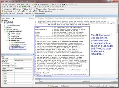
RMB on Solution -> Insert -> Commands
The analyst can then copy/paste the appropriate command block from above, which will execute immediately after the solution is done. See Figure 1 below. The IGES file will be created in that system’s working directory (e.g., c:\testproject\dp0\SYS<-1, -2, -3, etc.>\MECH).
To run macros in APDL, simply copy/paste the appropriate command script from above into a text file using Notepad, WordPad, or other text editor (note that commonly used word processor tools (e.g., Microsoft Word) cannot be used since word processor software embeds additional, hidden characters in the file contents, which are unrecognizable by Ansys). From the text editor software, save the macro. Then start an instance of APDL in any working directory with any job name. The IGES file will ultimately be created in that session’s working directory. The results file (.RST) may or may not need to be in that working directory. If the user left UPGEOM in its given syntax above (UPGEOM,1,,,FILE,RST), then the RST file will need to be in the session’s working directory with the name FILE.RST; or if the analyst has modified the file name and path correctly in field 5 of the UPGEOM command, there is no need to first place the RST file in the session’s working directory since the UPGEOM command will automatically go find the RST file. Click File > Read Input From to read the saved macro and it will process. There is no need to first read in the database (.DB) and .RST files; the macro takes care of everything.
Troubleshooting | Exporting a Deformed Geometry Shape
Any of the command sets may fail in the event the model contains some highly distorted elements. Granted, the command sets are intended to work on deformed geometry. But in some cases, a given model may be excessively loaded, relatively speaking, causing severe element deformation. To test if this is the cause of failure, simply rerun the model with less loading to determine if an IGES file is created.
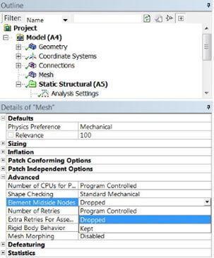
With regards to “Program Controlled” midside node options in Workbench Mechanical, it is often useful to override this by setting the model to have or not have midside nodes. See Figure 2 below.
This way, a user knows for sure one way or the other whether the model used 1st or 2nd order elements.
Conclusions | Exporting a Deformed Geometry Shape
A typical Workbench user is not usually aware of the powerful APDL command language that exists at their disposal. CDOPT and CDWRITE are valuable tools to extract model data into file formats that can be read in other software for further post-processing with other team members or perhaps vendors. This can really streamline the design process, reduce cost, and decrease the product’s time-to-market. The command language presented herein teaches the user how to export a loaded, deformed model shape to an IGES file format that is readable by many other commercial CAD software.
Contact for Additional Ansys Mechanical and/or Deformed Geometry Computations
Finally, we hope that you can make productive use of exporting a deformed geometry shape, and varying supportive commands/assignments for your Ansys Mechanical models. For more information, or to request engineering expertise for a particular use-case scenario surrounding geometric shape deformation, explicit dynamics, or general APDL commands, please contact us here.


