Introduction
Hot tearing, also frequently referred to as solidification cracking, represents one of the most significant challenges in modern foundries. These defects occur when the metal is in a semi-solid state, characterized by a fragile network of solid crystals surrounded by thin films of liquid. If the cooling part experiences tensile stress during this window (whether from the geometry of the part itself or the rigidity of the mold) these liquid films pull apart, leaving behind internal or external fractures.
The primary reason hot tearing is so detrimental to a project is that it is a late-stage failure. Often, these cracks are only discovered during non-destructive testing or final machining, long after the costs of raw materials, energy for melting, and labor for mold preparation have been realized. Utilizing simulation during the design phase provides a powerful proactive alternative to the traditional “pour and pray” method. By validating the casting design and the mold setup digitally, engineers can identify regions prone to lingering in the mushy zone, allowing them to optimize the process before a single physical tool is cut. This preemptive approach significantly reduces scrap rates, prevents expensive rework cycles, and ensures that production schedules remain on track by getting the design right the first time.
What is Hot Tearing?
To effectively prevent hot tearing, we must look closer at the physics of the “mushy zone.” As the introduction noted, this defect occurs when the metal exists as a semi-solid skeleton. During this specific window of time, the solid crystals (dendrites) have grown enough to touch and interlock, but they are still lubricated by thin films of residual liquid.
The transition from a liquid to a solid is rarely instantaneous; instead, it happens over a temperature range where the material’s structural integrity is at its most precarious. The risk of cracking becomes critical when three factors align:
- Contraction and Constraint: As the cooling metal naturally shrinks, it pulls against the mold or other thicker sections of the casting. This creates a strain demand on the fragile, semi-solid network.
- Separation of Liquid Films: If the tensile stress becomes too great, it pulls the liquid films apart between the dendrites.
- Failed Healing: In a perfect scenario, nearby liquid metal would flow into these micro-separations to “heal” them. However, during the final stages of freezing, the pathways for this liquid are often too narrow or disconnected.
When the strain exceeds the strength of this semi-solid skeleton and the feeding pathways are blocked, those separations evolve into the permanent, costly cracks we recognize as hot tears. By focusing our simulation efforts on this specific “vulnerable stage,” we can pinpoint exactly where the balance between strain and healing capacity is most likely to fail.
The Root Causes: Why Some Areas Crack
Most hot tears are driven by three main factors:
- Mushy-Zone Duration: The longer a region stays in that “vulnerable stage,” the more time it has to accumulate strain while its strength is at its lowest.
- Hot Spots and Constraints: Geometry transitions (thick-to-thin sections) and junctions tend to localize strain. When these hot spots contact a rigid mold, the contraction is resisted, pulling the material apart.
- Feeding Limitations: As the metal reaches the end of freezing, the pathways for liquid metal to flow and heal cracks become blocked.
The Workflow: Ansys Mechanical + QuesTek
A critical first step in predicting hot tearing is setting the right expectations for the simulation tool. It is important to note that Ansys Mechanical is not a fluid dynamics (CFD) solver; it does not model the turbulent flow of liquid metal, free-surface behavior during the pour, or the entrapment of air. However, for hot tearing analysis, the most vital piece of the puzzle is what happens after the mold is filled: the cooling and solidification phase.
Ansys Mechanical is top-notch at computing the transient thermal history of the entire system, the casting and the mold combined. This temperature-over-time data acts as the “DNA” of a hot tear study. Because hot tearing is a localized event driven by how a specific region cools relative to its neighbors, having a high-fidelity thermal map is non-negotiable.
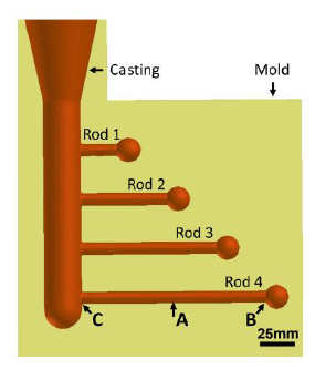
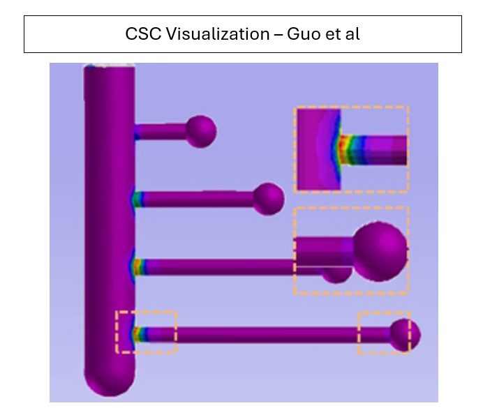
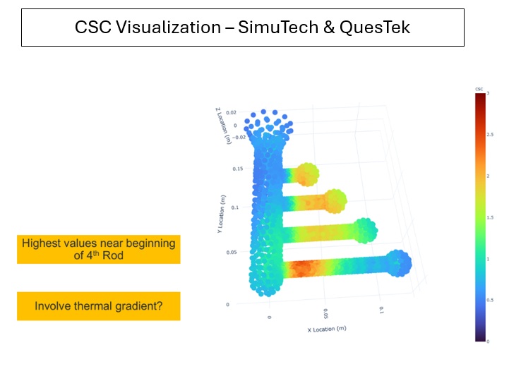
By leveraging Ansys Mechanical on a practical example, we can capture the complex thermal interactions that lead to defects. To do this, we will investigate the simple aluminum model before with varying rod lengths. This model was also investigated in Xiaopeng et al1, which we will use as a comparison to our simulation results.
Step 1: Thermal Simulation in Ansys Mechanical
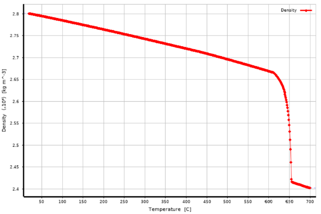
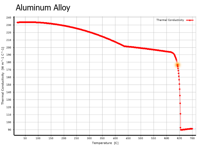
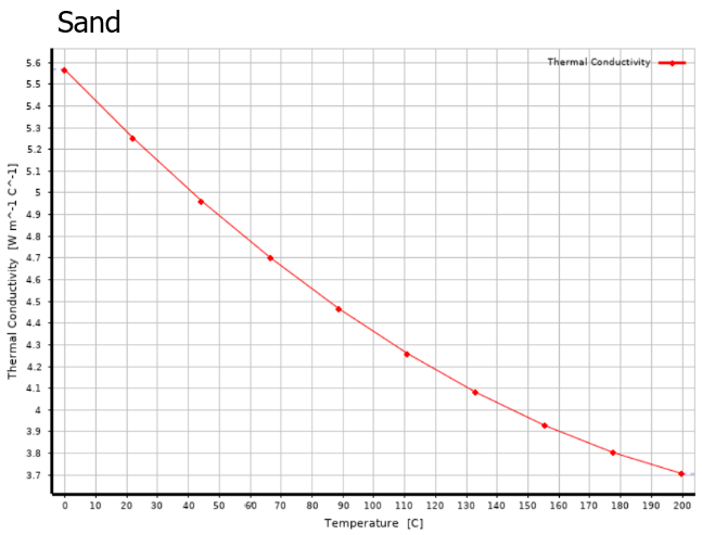
In this example, we define the material behavior by navigating to the Engineering Data tab and adding the following three essential properties:
- Density: Aluminum Alloy entered as a constant or temperature-dependent table to account for mass distribution. For the sand, we are not as interested, so we can insert it as just a constant, 2436 kg/m3.
- Isotropic Thermal Conductivity: Defined as a function of temperature to simulate how heat transfers through the material as it warms or cools.
- Specific Heat (Constant Pressure): Input as a property curve to define the aluminum alloy’s heat storage capacity during transient phases. For the sand, we are not as interested, so we can insert it as just a constant, 879.1 J/kgC
By using these specific inputs, the model can accurately calculate the internal energy changes and temperature distribution during the heat-up and cool-down sequences.

Step 2: Mechanical Model Setup
Once the materials have been created, we can move into Mechanical. The process to setup a typical transient analysis in Mechanical is as follows:
- Define Materials to Each Part: Select the Casting and Mold parts, and assign them to the Aluminum Alloy and Sand materials, respectively
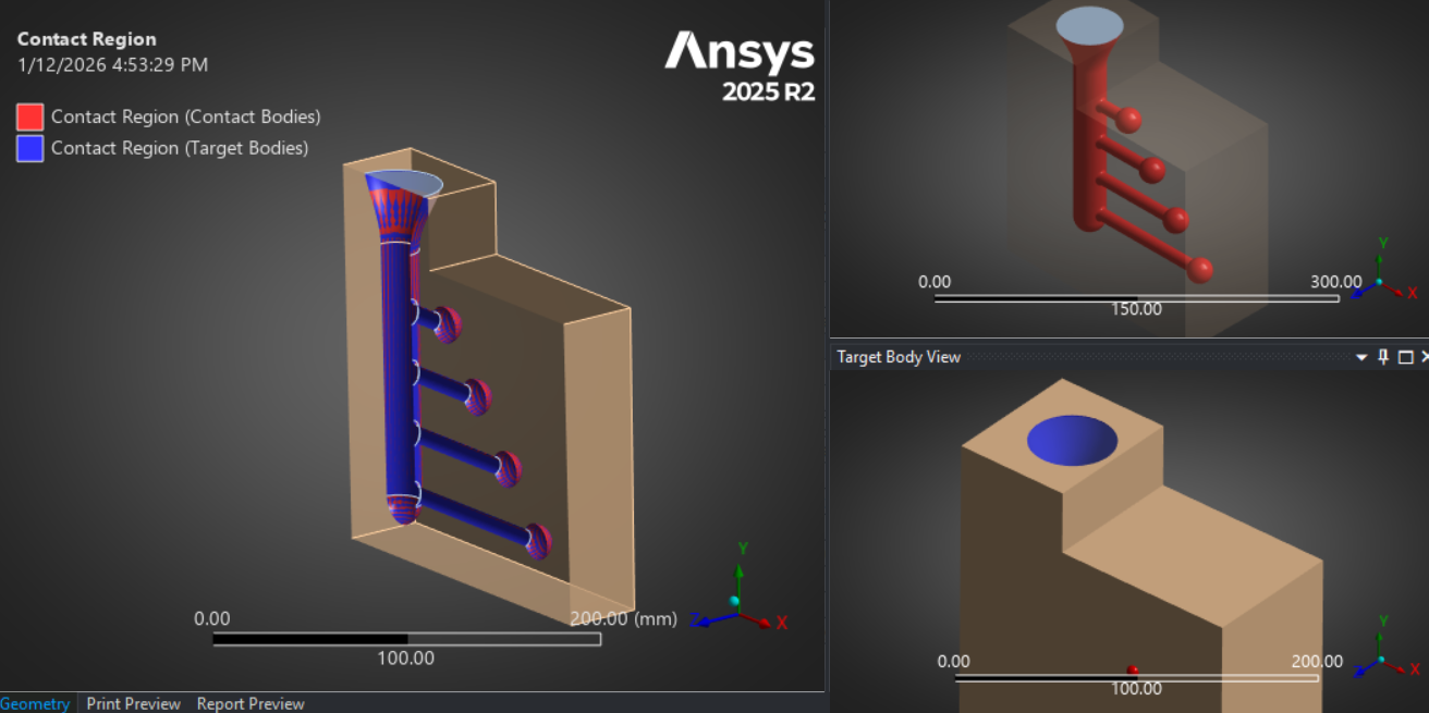
- Define any Connections: In this example, we are not leveraging Shared Topology, which connects parts via the mesh. As such, we’ll need to use a contact region in order to ensure heat is transferred from the casting to the mold.
- Generate Mesh: We need to generate the mesh on our model so that we can calculate the solution. Since this is an example hot tearing model, we will use a relatively coarse mesh. The model is set to use linear elements, with the capture curvature option activated such that it will refine smaller areas (joints, fillets, etc).
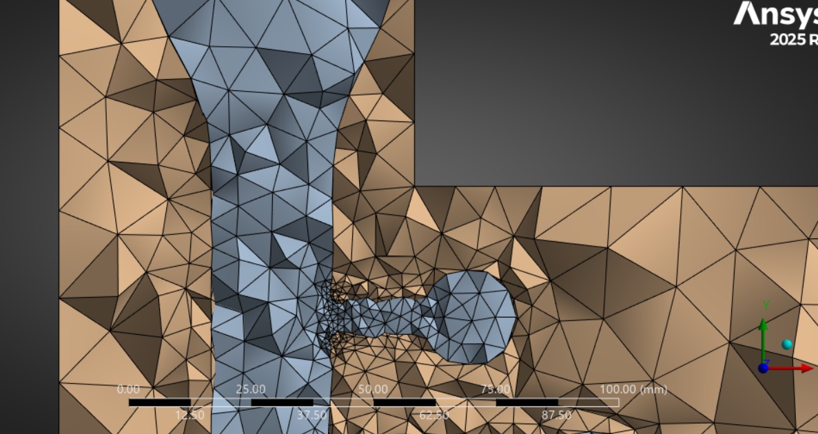
- Define Boundary Conditions: Since this is a transient model, we will have transient boundary conditions. The boundary conditions we will add are shown below:
- Initial Temperature: 250 C (To give the sand mold a smaller temperature gap with the aluminum cast and reduce thermal shock)
- Temperature: Aluminum should be set to 710 C at time 0 until time 0.1 seconds. This is to represent the temperature of the aluminum after it’s poured into the mold. After time 0.1 seconds, it the temperature boundary condition should be deactivated so that it may cool. This can be done in Mechanical by selecting the Temperature boundary condition, selecting the rows in the table you wish to deactivate, right clicking and selecting “Activate/Deactivate this step!”
- Convection: A convection boundary condition is added to the external surfaces of the mold, such that we can account for natural convective heat loss from the exposed surfaces to the external environment. Here, the film coefficient is 5 W/mC and the ambient temperature is 25 C.
- Radiation: Since heat may also be lost from radiation, we also include a radiation boundary condition so heat loss may be accounted for. Here, the emissivity is 0.7 and the ambient temperature is 25 C.
- Analysis Time Settings: In the Analysis Settings, it should be specified that this is a 2 step analysis. The first load step ends at time 0.1 seconds and will utilize automated time stepping. The second load step ends at 300 seconds and also leverages automatic time stepping.
Step 3: Results Export
Once the transient thermal solve is complete, the focus shifts from general cooling curves to the high-resolution data required for metallurgical analysis. At this stage, we extract the comprehensive thermal history for the entire geometry, capturing the exact temperature and heat flux for every node at every individual time step.
This data acts as the primary input for our collaboration with QuesTek. By post-processing these results, we provide the QuesTek team with a precise “thermal map” of the solidification process. They then utilize this data to perform a Scheil-diffusion calculation, which is a sophisticated non-equilibrium solidification model.
This calculation is the critical link in our workflow. It allows us to transition from simply knowing the temperature of the metal to understanding its physical state. Specifically, how the fraction of solid metal evolves over time for your specific alloy chemistry. By looking at the heat flux and temperature gradients together, we can identify not just how cold the part is, but how much energy is moving through the “mushy” regions where hot tears are born.
Step 4: The Scheil Calculation (The QuesTek Edge)
Once we have the thermal history from Mechanical, we want to understand how prone each section is to hot tearing. This is where our Technology Partners at QuesTek come in.
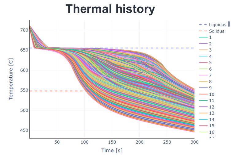
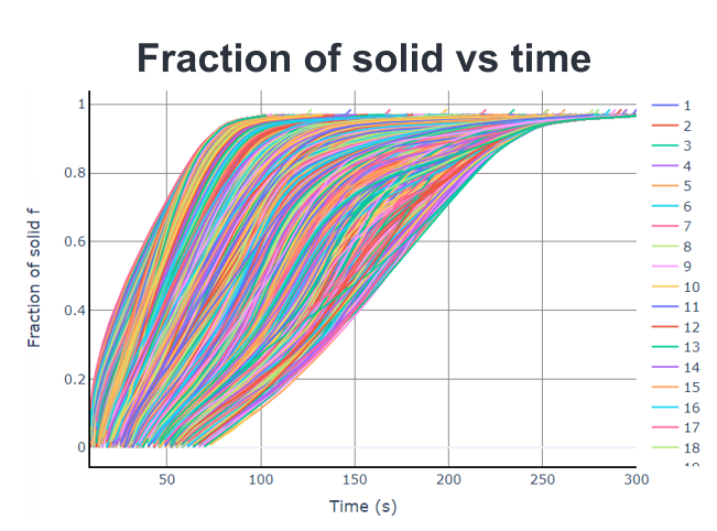
Using thermodynamic and kinetic databases, QuesTek performs a Scheil solidification calculation. This model produces solidification curves that depict the amount of time a given portion of your cast is spent in vulnerable stages of solidification. This is what will give us the visual for where our cast is most prone to hot tearing.
Mapping the Risk (CSC Metrics)
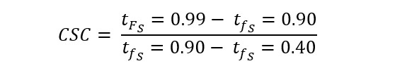
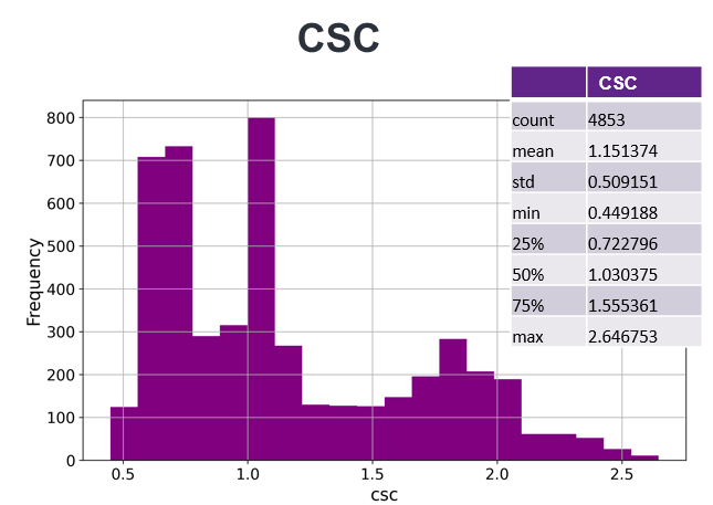
By combining the Ansys thermal history with the QuesTek solidification curve, we can calculate a Cracking Susceptibility Coefficient (CSC).
One common metric is the ratio of time spent in the “vulnerable” late-stage solidification (fS = 0.9 to 0.99) versus the time spent in the earlier growth stage. Regions with a high CSC are your “red zones”, or areas where the geometry lingers in a fragile state too long.
Turning Data into Better Designs
The goal isn’t just to find cracks, but also to prevent them. Once you’ve identified high-risk regions in your simulation, you have several “levers” to pull:
- Geometry Tweaks: Add fillets or smooth out thick-to-thin transitions to reduce strain localization.
- Thermal Management: Use local chills in the mold to speed up solidification in a hot spot, or add insulation to change the cooling direction.
- Gating Changes: Redesign the feeding system to ensure liquid metal can reach the vulnerable zones longer.
Hot Tearing, In Conclusion
By leveraging Ansys Mechanical to establish a precise thermal foundation for your process and integrating QuesTek’s metallurgical intelligence to decode your alloy’s behavior, you effectively remove the guesswork from the foundry floor. This integrated workflow allows you to move away from the expensive and time-consuming cycle of guess and check work and shift toward a culture of “predicting and perfecting.”
As a preliminary check, it is also possible to leverage Ansys Mechanical alone to perform a high-level estimate of risk. By focusing on the time it takes for various regions to pass through the liquidus-to-solidus temperature range, you can quickly identify “lazy” solidification zones that linger longer than the rest of the part. While this doesn’t offer the specific metallurgical depth of a full Scheil calculation, it provides an immediate, actionable glance at where your geometry might be working against you.
Ultimately, identifying these high-risk regions early in the design phase does more than just prevent cracks; it provides a roadmap for continuous improvement. Whether you are optimizing a complex ribbed bracket or scaling up production for a new aerospace component, these insights empower you to make data-driven decisions that safeguard your schedule, your budget, and the structural integrity of your parts.
Want to map hot tearing risk in your next casting design?
Talk with an FEA engineer to evaluate your thermal history, pinpoint CSC hot spots, and turn simulation results into actionable design changes.

Samuel Lopez, MS Mechanical Engineering
Strategic Account Engineer, SimuTech Group
Samuel Lopez is a Strategic Account Engineer at SimuTech Group with experience supporting industrial customers through CFD and FEA-driven simulation workflows. He specializes in computational fluid dynamics and finite element modeling using Ansys Fluent, Ansys CFX, Ansys Mechanical/APDL, and Ansys Sherlock, with additional experience in STAR-CCM+, OVERFLOW, and Chemkin. Prior to joining SimuTech Group, Samuel spent nearly seven years at Ozen Engineering in customer-facing technical roles spanning Application Engineer, Technical Support Administrator, and Technical Account Manager, helping teams adopt and troubleshoot simulation tools and best practices. His earlier research work at the Center for Energy and Environmental Research and Services included patient-specific 3D model development from CT scans for CFD studies, as well as advanced turbulence modeling (URANS, LES, and DES) and aerodynamic drag reduction research resulting in ASME conference publications. Samuel holds an M.S. and B.S. in Mechanical Engineering from California State University, Long Beach, and has completed Ansys training in Sherlock and PyMAPDL.
- Zeng, Xiaopeng, et al. “Effect of Li Content on Hot-Tearing Susceptibility of Ternary Al-Cu-Li Alloys: Experimental Investigation, Criterion Prediction, and Simulation Assessment.” Metallurgical and Materials Transactions A, vol. 54, no. 12, Dec. 2023, pp. 4850–67. SpringerLink, https://doi.org/10.1007/s11661-023-07207-5.