How to Map Stresses and Assign Node Locations in Ansys Mechanical with APDL Commander, *MOPER
Users can employ APDL commands to map stresses from one Ansys Mechanical APDL model to another, when the two models occupy the same geometry. There are also ways to do this in the Ansys Workbench environment, using the External Data system. This article illustrates how to map stresses in APDL, providing example APDL code to carry out the mapping. Note that the *MOPER and /INISTATE commands are essential in carrying out the mapping efficiently.
Users sometimes want to map stresses from one model into another. There are tools to do this in both Ansys Mechanical APDL, as well as using External Data in Ansys Workbench Mechanical. This document explores using APDL commands.
Corner Nodes in an FEA Analysis
An array of node locations and an array of stress components can be created for corner nodes in an Ansys FEA result. There is an APDL command called *MOPER that can be used to map those stresses to the locations of another set of coordinates that fit inside and on the boundary of the original set of nodes. This facility can be used to map stresses from one model to another, when the receiving model fits the same geometry.
To proceed with the original model, *VGET commands will quickly retrieve node locations and stresses, placing them in arrays. The command *VWRITE can write the coordinate and stress data to ASCII text files for later use.
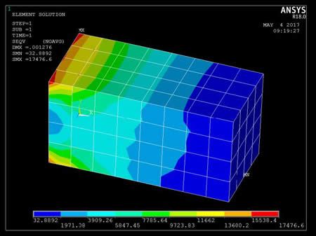
The following set of APDL commands builds and solves the example model seen in the left image in Figure 1, above, and moves its corner node locations and stresses into data array columns:
fini
/clear,nostart
!
! Create a block. Mesh with hex elements. Fix the left side, place pressure on top and Solve.
! Use at your own risk. . .
/PREP7
ET,1,SOLID186
MPTEMP,,,,,,,,
MPTEMP,1,0
MPDATA,EX,1,,30000000
MPDATA,PRXY,1,,.3
BLOCK,,2,,1,,1,
/VIEW,1,1,2,3
/ANG,1
/REP,FAST
ESIZE,1/4,0,
MSHAPE,0,3D
MSHKEY,1
!*
CM,_Y,VOLU
VSEL, , , , 1
CM,_Y1,VOLU
CHKMSH,’VOLU’
CMSEL,S,_Y
!*
VMESH,_Y1
!*
CMDELE,_Y
CMDELE,_Y1
CMDELE,_Y2
!*
FINISH
/SOL
FLST,2,1,5,ORDE,1
FITEM,2,5
!*
/GO
DA,P51X,ALL,
FLST,2,1,5,ORDE,1
FITEM,2,4
/GO
!*
SFA,P51X,1,PRES,1234
solve
FINISH
!
! Plot equivalent stress
/POST1
/efacet,2 ! more detail
plnsol,s,eqv
! SAVE A COPY TO LOOK AT LATER
/UI,COPY,SAVE,PNG,GRAPH,COLOR,NORM,PORTRAIT,YES,9
plesol,s,eqv
/UI,COPY,SAVE,PNG,GRAPH,COLOR,NORM,PORTRAIT,YES,9
/wait,1
!
! reselect nodes at corners only. No stresses at midside nodes
nsle,r,corner
!
! Create arrays to hold node coordinates and stress components
*get,maxnode,node,,num,max ! highest node number
*get,numnodes,node,,count ! number of selected nodes
!
*del,nc,,nopr
*del,ns,,nopr
*del,mymask,,nopr
!
*dim,nc,array,maxnode,3 ! node coordinates x,y,z
*dim,ns,array,maxnode,6 ! node stress components
!
! Create a node masking array for further array work in case
! node numbering is not continuous, or nodes are not selected.
*dim,mymask,array,maxnode
*vget,mymask(1),node,1,nsel ! fill with status values
!
! *VGET coordinates of the nodes
*vmask,mymask(1)
*vget,nc(1,1),node,1,loc,x
*vmask,mymask(1)
*vget,nc(1,2),node,1,loc,y
*vmask,mymask(1)
*vget,nc(1,3),node,1,loc,z
!
! *VGET stress components of the nodes
*vmask,mymask(1)
*vget,ns(1,1),node,1,s,x
*vmask,mymask(1)
*vget,ns(1,2),node,1,s,y
*vmask,mymask(1)
*vget,ns(1,3),node,1,s,z
*vmask,mymask(1)
*vget,ns(1,4),node,1,s,xy
*vmask,mymask(1)
*vget,ns(1,5),node,1,s,yz
*vmask,mymask(1)
*vget,ns(1,6),node,1,s,xz
!
! Compress out the midside node zeros…
! Want ns2 array to contain stress components at locations in nc2 array
!
*del,nc2,,nopr
*del,ns2,,nopr
*dim,nc2,array,numnodes,3 ! compressed file of coordinates
*dim,ns2,array,numnodes,6 ! compressed file of stresses
*do,ii,1,3 ! compress 3 coordinates
*vmask,mymask(1)
*vfun,nc2(1,ii),COMP,nc(1,ii)
*enddo
*do,ii,1,6 ! compress 6 stresses
*vmask,mymask(1)
*vfun,ns2(1,ii),COMP,ns(1,ii)
*enddo
!
INISTATE Command | Resulting Stress Values at the Receiving Model Nodes
A second receiving model as in the right hand image of Figure 1 can have the stresses mapped in as initial conditions using its own node coordinates. The node locations of the receiving model can be loaded into an array with *VGET commands. The *MOPER command can map stress values of the original model into the node locations of the receiving model, using the arrays. Finally the INISTATE command can place the resulting stress values at the nodes of the receiving model.
The following APDL commands re-mesh the above geometry with an alternative mesh, move node locations to array columns, map stresses from the original model with *MOPER, and move the stresses to the new mesh with INITATE commands. The nodes are constrained in all degrees of freedom, the model is solved, and the mapped stresses are displayed. Note that there is not displacement in the receiving model result since all nodes are constrained:
! Now, remesh with tet mesh, and map stresses to nodes using *MOPER to map,
! and INISTATE to place stresses in the undeformed mesh
! Stresses applied to midside nodes will be ignored in Solve
!
FINISH
/PREP7
vclear,1 ! clear the mesh
dadele,all,all ! remove constraint
sfadele,all,all,all ! remove pressure
MSHAPE,1,3D
MSHKEY,0
!*
CM,_Y,VOLU
VSEL, , , , 1
CM,_Y1,VOLU
CHKMSH,’VOLU’
CMSEL,S,_Y
!*
VMESH,_Y1 ! mesh with tetrahedrons
!*
CMDELE,_Y
CMDELE,_Y1
CMDELE,_Y2
!*
! Create array of node locations in tet elements, and array for mapped stresses.
*del,nc3,,nopr
*del,ns3,,nopr
!
*get,maxnode3,node,,num,max ! highest node number
*dim,nc3,array,maxnode3,3 ! node coordinates x,y,z of new mesh
*dim,ns3,array,maxnode3,6 ! node stress components of new mesh
!
! *VGET coordinates of the new nodes
*vget,nc3(1,1),node,1,loc,x
*vget,nc3(1,2),node,1,loc,y
*vget,nc3(1,3),node,1,loc,z
!
*MOPER,ns3(1,1),nc3(1,1),MAP,ns2(1,1),nc2(1,1),3 ! Map data from first mesh compressed data
!
fini
/solu
x3=maxnode3 ! highest node number, shorter name
inistate,set,NODE,1 ! node-based initial state
! Use implied looping for speed.
! Impose the 6 stress components with INISTATE on nodes 1 through x3
inistate,defi,(1:x3),,,,ns3(1:x3,1),ns3(1:x3,2),ns3(1:x3,3),ns3(1:x3,4),ns3(1:x3,5),ns3(1:x3,6)
d,all,all ! constrain all degrees of freedom
solve
fini
/post1
/efacet,2 ! more detail
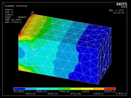
plnsol,s,eqv ! how do the stresses look?
! Save a copy to look at later
/UI,COPY,SAVE,PNG,GRAPH,COLOR,NORM,PORTRAIT,YES,9
plesol,s,eqv
/UI,COPY,SAVE,PNG,GRAPH,COLOR,NORM,PORTRAIT,YES,9
*msg,UI
See the working directory to compare the four plots
In the event that the node coordinates and stresses from the first model need to be written to an external file, the following commands illustrate how it can be done. Numerical data here has been written with 14 digit accuracy:
! Write compressed coordinate and stress arrays to exterior files.
! The format used writes 14 digits for each numerical entry
! Open the file to be written, then *VWRITE the coordinate columns
/nopr
*cfopen,xyz_data,txt
*vwrite,nc2(1,1),nc2(1,2),nc2(1,3)
(3E23.14)
*cfclos
!
! Open the file to be written, then *VWRITE the stress component columns
*cfopen,stress_components,txt
*vwrite,ns2(1,1),ns2(1,2),ns2(1,3),ns2(1,4),ns2(1,5),ns2(1,6)
(6E23.14)
*cfclos
/gopr
!
To read the coordinate and stress data into arrays in a second model, the following commands illustrate a method:
! To read coordinate and stress array data from files created above…
! Delete the arrays if they exist
*del,nc_in,,nopr ! hold coordinates
*del,ns_in,,nopr ! hold stress components at the coordinates
!
! How many rows in one of these files? Dimension arrays accordingly.
/INQUIRE,numlines,LINES,xyz_data,txt
*dim,nc_in,array,numlines,3 ! coordinate data array
*dim,ns_in,array,numlines,6 ! 6 stress components array
!
! *VREAD data from the coordinate and stress component files
*vread,nc_in(1,1),xyz_data,txt,,JIK,3,numlines,1
(3E23.14)
*vread,ns_in(1,1),stress_components,txt,,JIK,6,numlines,1
(6E23.14)
!
As shown in the first APDL example, to check the mapped stress values in the receiving model, a user can constrain all degrees of freedom in the receiving model, remove any other loads, and solve. If the material properties are linear, the mapped stress values should be available to list and plot as results over the model.
If only the constraints of the original model are applied to a receiving model that differs only in the mesh, then when solved, and equal but opposite deflection should be seen, within the accuracy that might be expected from the meshes that have been used.
Note the important APDL commands that we have employed above:
*GET
*VGET
*VMASK
*VFUN
*MOPER
/INISTATE
Ansys APDL Commands Manual | Ansys Help Downloadable PDF
These commands can be studied in detail in the Commands Manual in the Ansys Help system.
Users can adapt the methods illustrated here to map various quantities between models that fit the same geometry. Users should check for correctness and accuracy of the methods employed.
Contact for Additional Ansys Mechanical and/or APDL Support
Finally, we hope that you can make productive use of the Ansys APDL *MOPER command, and varying supportive commands/assignments for your Ansys Mechanical models. For more information, or to request engineering expertise for a particular use-case scenario surrounding *MOPER, APDL commands or Node Assignments, please contact us here.