Contact Us
Learn how to use the Ansys Fluent 3D Fan Zone to represent fan performance without explicitly modeling rotating blades, reducing geometric complexity and computational cost in system-level CFD simulations.
Introduction
Fans are widely used in engineering applications such as HVAC systems, cooling equipment, drying processes, and air-handling systems. In CFD simulations, however, explicitly modeling the fan blades is not always necessary, particularly when the main objective is to predict the overall flow behavior rather than the detailed aerodynamics around the blades.
Ansys Fluent provides a convenient alternative through the 3D Fan Zone, which allows the effect of a fan to be represented within a cell zone without explicitly modeling its geometry. By defining the fan performance characteristics, such as the pressure rise as a function of flow rate, the 3D Fan Zone can provide an efficient representation of the fan while reducing geometric complexity and computational cost.
The Issue
Explicitly modeling a fan in CFD requires creating and meshing the blades and surrounding geometry, which can significantly increase the complexity and computational cost of the simulation. In addition, accurately capturing the rotating flow generated by the blades may require more advanced modeling approaches, such as a rotating reference frame or transient simulations.
This level of detail is often unnecessary when the objective is to evaluate the overall system performance, such as airflow distribution, pressure drop, or the interaction between the fan and other components. A simplified approach is therefore desirable when the detailed flow field around the fan blades is not of primary interest.
Setting Up an Ansys Fluent 3D Fan Zone
The following example demonstrates how a 3D Fan Zone can be used to represent an axial fan within a closed-loop wind tunnel system. The model uses air as the working fluid and includes the main components of the system, such as the fan, elbows, contraction, diffuser and working section.
Instead of explicitly modeling the fan blades, the fan is represented using a dedicated cell zone that applies the fan performance characteristics to the flow. This approach simplifies the geometry and allows the overall flow behavior through the system to be evaluated with reduced modeling complexity.
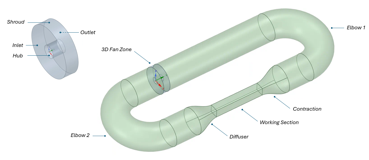
In this case, it is a simple subsonic wind tunnel, intended only to demonstrate the use of the 3D Fan Zone. In the geometry, the use of Share Topology is recommended to ensure a conformal mesh between adjacent bodies. After creating the mesh in Ansys Meshing or Ansys Fluent Meshing, the model setup continues in Fluent.
Define the 3D Fan Zone and Fan Performance Data
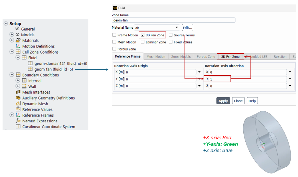
The model setup includes the turbulence model, material, and boundary conditions. It is worth noting that there is no inlet or outlet boundary condition in this case. Instead, the 3D Fan Zone is defined in the corresponding Cell Zone for the annular cylinder representing the fan. The following figure shows the dialog box with the required information:
- Enable the 3D Fan Zone.
- Define the rotation-axis of the fan. For this geometry, it is the Y-axis.
- Go to the ‘3D Fan Zone’ Tab.
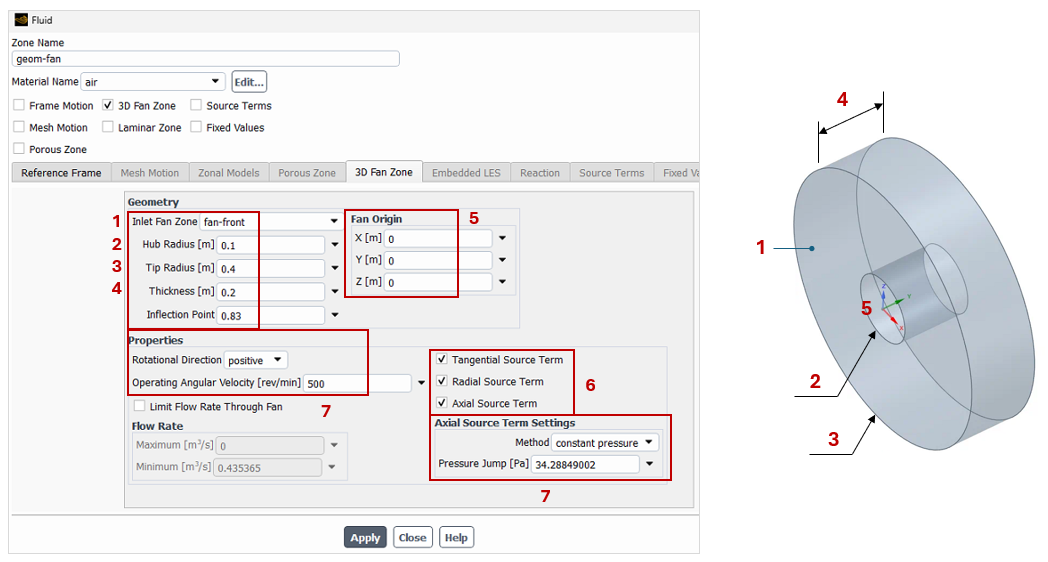
1. Select the inlet surface of the fan/blower. This must have a name selection from geometry.
2-4. Provide the dimensions of the annular cylinder.
5. Define the origin location of the fan.
6. Specify the velocity components of the velocity (source terms).
7. Specify the fan data in Ansys Fluent:
- Constant pressure. It requires the definition of the ΔP generated by the fan at the operating speed.
- Fan curve. Using a fan curve provides a more realistic operating point because the simulation accounts for system resistance and secondary losses.
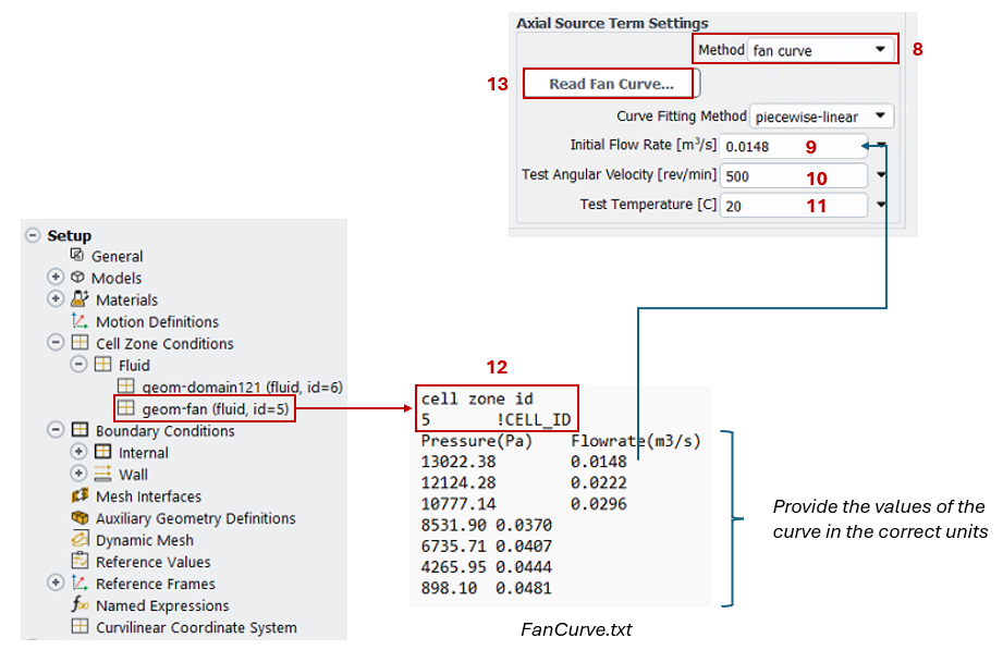
In case you want to upload the fan curve:
8. Change the ‘Method’ to ‘Fan Curve’.
9. Provide the lowest volumetric flow rate of the curve.
10-11. Specify the nominal rotational speed and the test temperature (from the curve).
12. Make sure the ID of the cell zone is defined in the text file.
13. Prepare the file using the syntax shown below including all values in the same units of the Fluent project. Upload the file. Click on Apply and close the dialog box.
Before solving the simulation, it is recommended to monitor the key variables, such as the minimum, average, and maximum velocity, temperature, etc. Once the simulation is solved, the results can be post-processed as shown below.
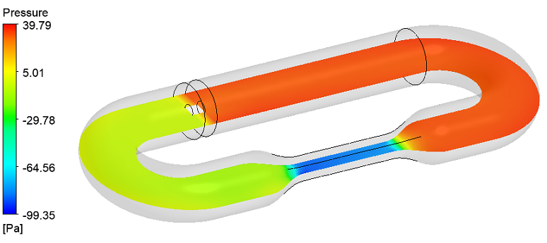
Static pressure. The results of our Ansys Fluent 3D fan zone simulation show how the fan adds energy to the fluid, increasing the pressure downstream of the fan.
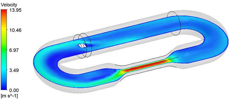
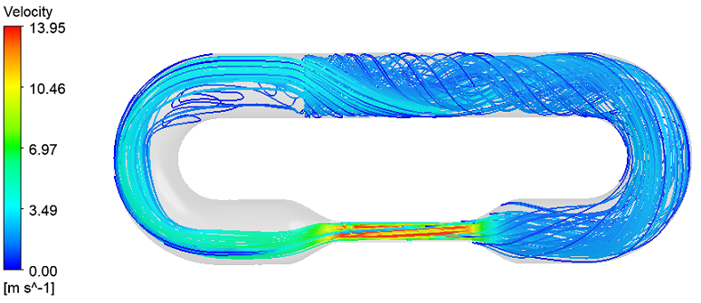
Velocity. Using contours and streamlines, it is possible to identify regions where the flow is non-uniform and where additional components may be needed to control the flow through the circuit. The main objective is to achieve a uniform velocity at the entrance of the working section.
Conclusion: When to Use an Ansys Fluent 3D Fan Zone
The 3D Fan Zone provides a simple and effective way to model fan performance without explicitly modeling the rotating components. The setup is performed in the Cell Zone representing the fan or blower, following the steps described above. This approach is useful for applications involving closed-loop systems, HVAC, ventilation systems, and other similar applications.
Need help modeling fans or airflow systems in Ansys Fluent?
SimuTech Group’s Fluids engineers can help your team set up Ansys Fluent fan simulations, evaluate fan curves and operating points, and analyze airflow, pressure drop, and system performance in HVAC, ventilation, cooling, and other air-handling applications. Connect with SimuTech Group to discuss your CFD project.

Germán Ibarra, MSc Energy Engineering
Senior Staff Engineer – Fluids, SimuTech Group
Germán Ibarra is a mechanical engineer with a master’s degree in Energy Engineering and more than 14 years of experience in research, development, and engineering analysis. At SimuTech Group, he supports simulation-driven workflows for complex engineering applications, including polymer processing, thermal-fluid behavior, and manufacturing process optimization. His background spans R&D, project development, and technical education, helping engineering teams apply numerical simulation to better understand product performance, reduce physical testing, and improve design decisions.