Contact Us
Learn how to generate a temperature field in Ansys Fluent, export interface temperatures through CFD-Post, and apply the resulting profile as a thermal boundary condition in an Ansys Fluent Polyflow extrusion simulation.
Introduction
Fluent Polyflow extends the capabilities of the Ansys Fluent environment to address complex polymer-processing applications by combining advanced CFD workflows with specialized rheological modeling. Designed to accurately represent viscoelastic and non-Newtonian materials, it enables engineers to simulate processes such as extrusion, blow molding, thermoforming, film casting, and fiber spinning while reducing reliance on costly trial-and-error experimentation.
By integrating virtual prototyping, advanced material models, adaptive meshing, fluid–structure interaction, and automated design optimization within the Fluent ecosystem, Fluent Polyflow helps accelerate product development, reduce material consumption, and improve manufacturing efficiency. These capabilities allow engineers to better understand material behavior and optimize polymer-processing operations before physical production begins.
The Issue
One of the main challenges in Fluent Polyflow simulations is their computational cost. Hardware requirements depend on factors such as mesh size, boundary conditions, and, especially, the rheological model used to describe the material. Since complex viscoelastic constitutive equations must be solved at every iteration, large three-dimensional models can require significant memory resources and long computation times.
A common strategy to reduce computational cost is to prescribe a temperature profile as a boundary condition instead of solving the complete thermal problem. While this approach can substantially reduce solution time without compromising engineering accuracy, Fluent Polyflow does not provide a straightforward workflow for implementing it in extrusion simulations. This article presents a simple workaround to overcome this limitation.
Using a Temperature Profile in Ansys Fluent Polyflow
Let’s consider the extrusion geometry shown below, which consists of two solid bodies (an outer die and an inner mandrel) and two fluid regions (the flow inside the die and the extrudate).
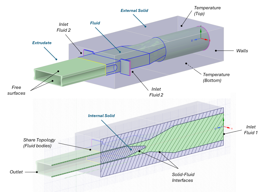
Solving this model in Fluent Polyflow can require a considerable amount of RAM, although the exact memory demand depends on several factors, particularly the mesh size and the material model. More complex geometries typically require finer meshes, while advanced rheological models increase the computational effort because the governing equations describing material properties, such as density and viscosity, must be solved throughout the computational domain at every iteration.
Ansys Fluent Polyflow Temperature Profile Workflow
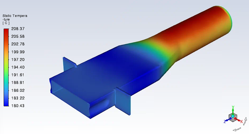
Fluent Simulation. For this example, the mesh was generated in Ansys Meshing within Workbench and consists of 2.36 million tetrahedral elements, although it could also be created using Fluent Meshing. The model is solved in Fluent without flow by disabling the momentum and turbulence equations and retaining only the energy equation. This significantly reduces the computational effort while providing the temperature field required for the extrusion analysis.
The material properties are then defined in Fluent using the same materials that will later be used in Fluent Polyflow, and the thermal boundary conditions are specified, including fixed temperatures and natural convection. Once the solution is complete, the temperature distribution is obtained throughout both the solid and fluid regions. The temperature values at the solid–fluid interfaces are then extracted in the CFD-Post and used to prescribe the thermal boundary conditions in the Fluent Polyflow extrusion simulation.
CFD-Post. Open the results file in CFD-Post and change the temperature units to Kelvin, which is the unit system used by Fluent Polyflow. Next, identify the solid–fluid interfaces and display the temperature contours on both surfaces to verify the temperature distribution. The next step is to export the temperature values for these interfaces so they can be used as boundary conditions in Fluent Polyflow. The required data can be extracted by following the steps described below.
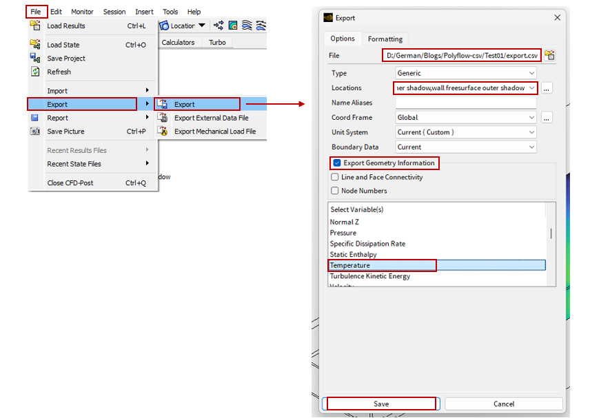
Go to File > Export > Export. First, specify the location where the file will be saved. Next, select the interfaces to export (those , which correspond to the outer walls of both fluid domains in the Fluent Polyflow model. Make sure the Export Geometry Information option is enabled, then select Temperature as the variable to export. Click Save and verify that the export csv file has been created in the selected location. This file contains the temperature distribution at the interfaces and will be used to prescribe the temperature boundary conditions in the Fluent Polyflow extrusion simulation.
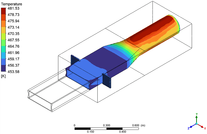
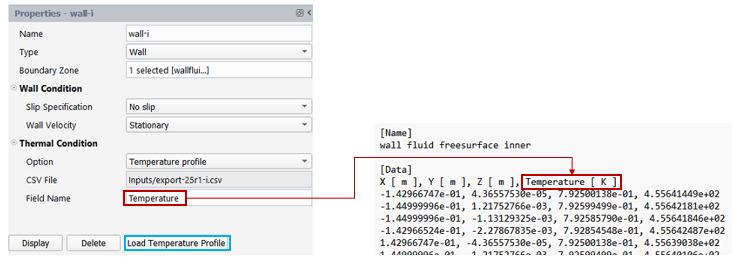
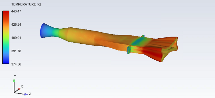
Fluent Polyflow. Create a mesh for the two fluid domains using Ansys Meshing within Workbench. In this case, the mesh consists of 598k tetrahedral cells, approximately 25% of the original mesh size. Import the mesh file and begin setting up the model. Once you reach the wall boundary conditions (two in this example), import the CSV file as shown below. Make sure that the Field Name specified in the boundary condition matches the corresponding field name in the CSV file. After solving the simulation, review the temperature results, this time including the deformation of the extrudate region.
Conclusion
If a full coupled thermal Polyflow model exceeds available hardware resources, this workflow provides a practical way to preserve the required temperature distribution while reducing the computational burden. Solve the thermal field in Fluent, export the solid-fluid interface temperatures through CFD-Post, and apply the resulting profile in the Polyflow extrusion model.
Need help with Ansys Fluent Polyflow extrusion simulations?
SimuTech Group’s Fluids engineers can help your team develop efficient Ansys Fluent Polyflow workflows for extrusion, thermal boundary conditions, rheological modeling, and other polymer-processing applications. Connect with SimuTech Group to discuss your simulation project.

Germán Ibarra, MSc Energy Engineering
Senior Staff Engineer – Fluids, SimuTech Group
Germán Ibarra is a mechanical engineer with a master’s degree in Energy Engineering and more than 14 years of experience in research, development, and engineering analysis. At SimuTech Group, he supports simulation-driven workflows for complex engineering applications, including polymer processing, thermal-fluid behavior, and manufacturing process optimization. His background spans R&D, project development, and technical education, helping engineering teams apply numerical simulation to better understand product performance, reduce physical testing, and improve design decisions.