Contact Us
Learn how to use the Ansys Motion bearing catalog to obtain stiffness properties and create a simplified bearing representation with a bushing joint in Ansys Mechanical.
Why Represent a Bearing with a Bushing Joint?
Representing a bearing as a bushing joint in Ansys Mechanical requires appropriate linear and rotational stiffness values. Those properties may come from manufacturer data or internal testing, but Ansys Motion also provides bearing geometry and stiffness information for many common bearing types.
Using those properties in a bushing joint provides a simplified way to capture bearing behavior in a static structural model without explicitly resolving the full bearing geometry. This can reduce model complexity and computational cost while preserving the stiffness behavior needed for the surrounding assembly.
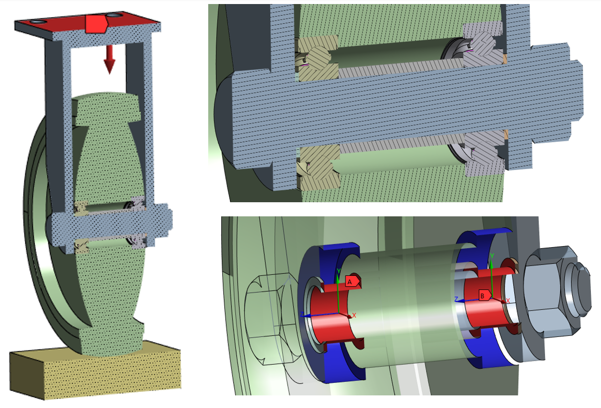
The example below uses a loaded caster wheel assembly with two ball bearings that are replaced with bushing joints.
How to Create a Bearing Bushing Joint in Ansys Mechanical
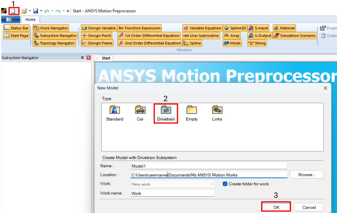
- Launch Ansys Motion Pre and create a new drivetrain file. Version 2025 R2 is used for this example.
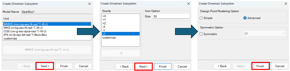
- Select units, then gravity direction, and finally modeling option (defaults shown below). Clicking Finish accepts defaults for the remaining options.
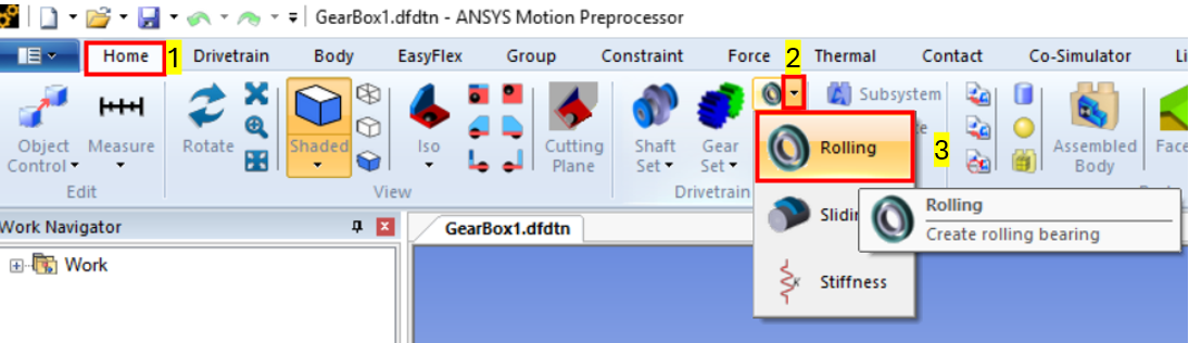
- From the Home or Drivetrain tab, click on the bearing dropdown menu and select rolling (other options are available, rolling is used for this Ansys Mechanical bushing joint example). The catalog allows the user to specify type, size and/or manufacturer to obtain desired bearing properties.
- Apply ranges to match bearing design criteria (Bore, outer diameter, etc.). Click apply once a desired bearing is found. Here we choose a ball bearing type with a 12 mm bore, 28 mm outer diameter, and a width of 8 mm. The bearing that matches these dimensions is shown at the top of the table.
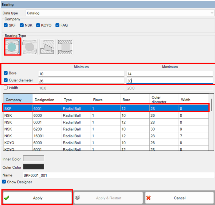
The “General,” “Dimensions,” and “Internal” provide more information on the bearing (damping ratio, number of bearing balls, etc.).
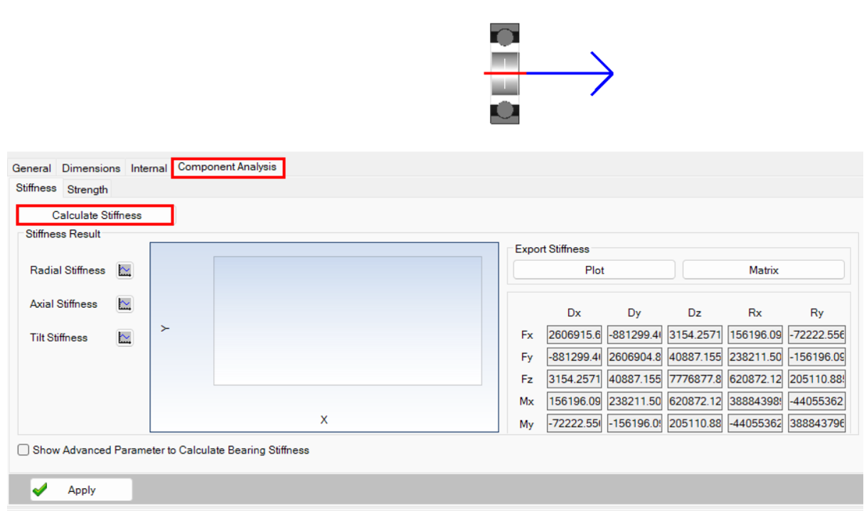
- Click on component analysis to calculate bearing stiffness coefficients to use for the bushing joint (verify that the units match between Motion and Mechanical!).
- Insert the stiffness coefficients in the worksheet view of the bushing joint in Mechanical
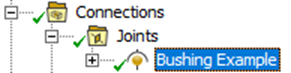

The bushing joint now has enough information to simulate a bearing in a static structural analysis.
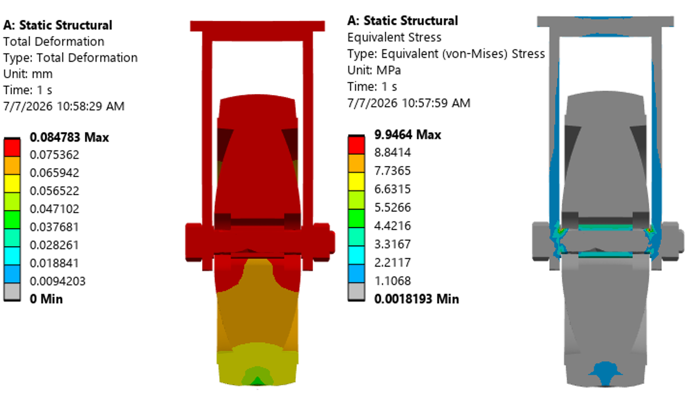
Using Ansys Motion Bearing Data in Static Structural Analysis
A perfect catalog match may not always be available, but the Ansys Motion bearing catalog can still help identify a bearing with geometry and stiffness properties close to the intended design. Those calculated stiffness coefficients can then be transferred into an Ansys Mechanical bushing joint to create a practical simplified bearing representation.
This workflow gives engineers another option for incorporating bearing behavior into static structural analysis without explicitly modeling every bearing component. As with manufacturer data or test-derived properties, the selected stiffness values should be reviewed to ensure they are appropriate for the intended application.
Need help simplifying bearing or joint behavior in Ansys Mechanical?
SimuTech Group’s Structural engineers can help your team develop efficient Ansys Mechanical models using joints, connectors, bearing representations, contact, and other idealization techniques. Connect with SimuTech Group to discuss your structural simulation project.

David Castellanos, PE
Staff Engineer – Structures, SimuTech Group
David Castellanos, PE, is a Staff Engineer in Structures at SimuTech Group with experience in finite element analysis, structural dynamics, and aerospace mechanical systems. His background includes structural analysis for aircraft, gas turbine engines, and spacecraft, with work in fatigue, fracture, stress analysis, and rotor dynamics. He holds B.S. and M.S. degrees in Mechanical Engineering from New Mexico State University and is a licensed Professional Engineer.