LTI reduced order models allow battery thermal engineers to evaluate usage cycle performance in seconds rather than hours. This blog walks through building Linear Time Invariant (LTI) ROMs for a battery module using Ansys Fluent for training and Twin Builder Digital Twin for real-time evaluation, comparing both SIMO and MIMO approaches.
Thermal Challenges in Battery Module Design for Usage Cycles
Designing battery modules for usage cycles presents several unique thermal engineering challenges:
- Dynamic load conditions: Usage cycles such as drive cycles involve variable loads, speeds, and environmental conditions, requiring batteries to deliver consistent performance under dynamic stress.
- Heat generation from fluctuating currents: Managing thermal behavior is critical, as fluctuating currents generate heat that can degrade cells.
- Competing design constraints: Designers must ensure strong energy density, power output, and safety while balancing size, weight, and cost constraints.
- Cell matching: Cells must be carefully matched to avoid imbalances that affect performance and lifespan.
- Long-term degradation prediction: Predicting long-term degradation under real-world cycling further complicates design.
Achieving durability, efficiency, and reliability across diverse driving scenarios demands careful engineering and advanced control strategies.
Engineering Strategies for Battery Module Thermal Management
To address battery module challenges in drive cycles, engineers employ several solutions. Thermal management systems, such as liquid cooling or phase-change materials, regulate temperature and prevent overheating. Battery management systems (BMS) monitor voltage, current, and temperature to ensure cell balancing and safe operation. Advanced modeling and simulation tools help predict performance and degradation under various drive conditions. Cell selection and matching improve uniformity and longevity. Structural design optimizes packaging for weight, durability, and crash safety. Additionally, adaptive control algorithms adjust power delivery in real time to enhance efficiency and extend battery life across diverse driving scenarios.
Why LTI Reduced Order Models Speed Up Battery Module Simulation
Ansys Fluent is an effective tool for evaluating battery thermal system solutions; however, these evaluations can present several challenges. Creating accurate models requires detailed input data, including material properties and cell behavior under various conditions, which can be difficult to obtain. Validating high-fidelity simulations in Fluent is computationally intensive and time-consuming when considering usage cycles. By leveraging Reduced Order Models in Ansys Digital Twin thermal solutions, usage cycles can be evaluated in real time. This blog addresses the Linear Time Invariant (LTI) Reduced Order Model (ROM) for a battery module.
Simulation Setup: Thought Map, Product Map, Fluent Training, and Twin Builder
Setting up a battery module thermal simulation with Ansys Fluent and Digital Twin involves several steps. These steps include a thought map, a product map, a Fluent case setup, and a Twin Builder Digital Twin setup.
Thought Map
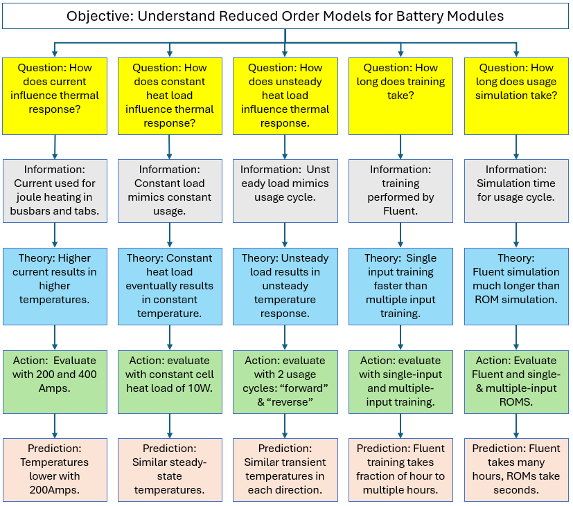
A thought map of battery modeling characteristics is generated to organize and represent ideas, concepts, or information in a structured way. The thought map below shows the simulation study’s objective and the questions asked to address it. Each question is followed by a theory, an action, and a prediction. Results would also be added to the bottom of each branch as they are generated.
Product Map
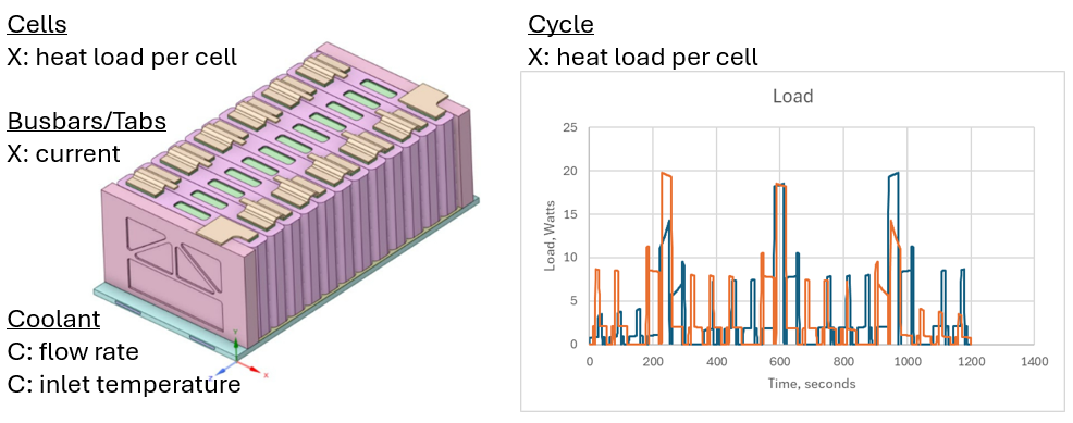
A product map of the battery module is generated to list and categorize product features. A product map indicates some factors that correspond to theories/actions in the thought map.
Fluent Training Simulation
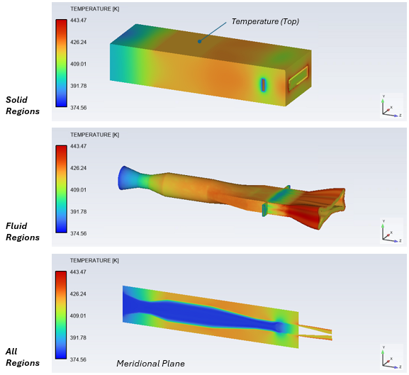
Fluent models are executed for training purposes per the studies produced by the thought map. A steady-state cold-flow simulation is performed first to generate a solution for the cold-plate coolant flow with zero-cell heat release and zero tab current. Then the flow equations are deactivated, and the energy equation is activated. The images below show the sequence of steps for training the LTI model with Single-Input Multiple-Output and Multiple-Input Multiple-Output Reduced-Order Models in the Fluent Battery Model.
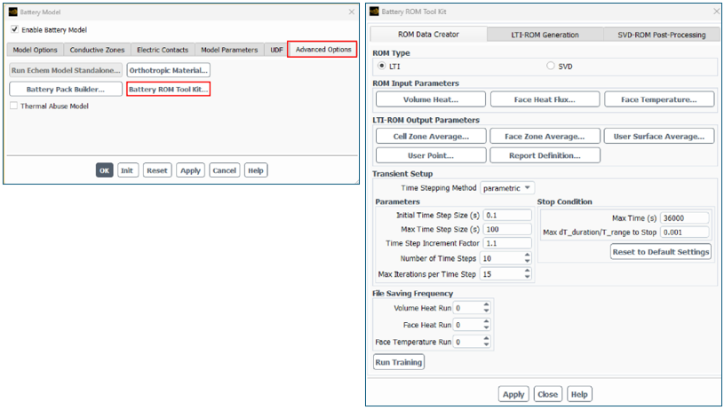
The following image shows the activation of the Battery ROM Tool Kit and the selection of the LTI ROM type from the Battery Model panel.
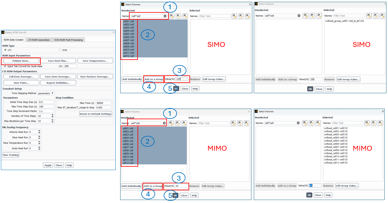
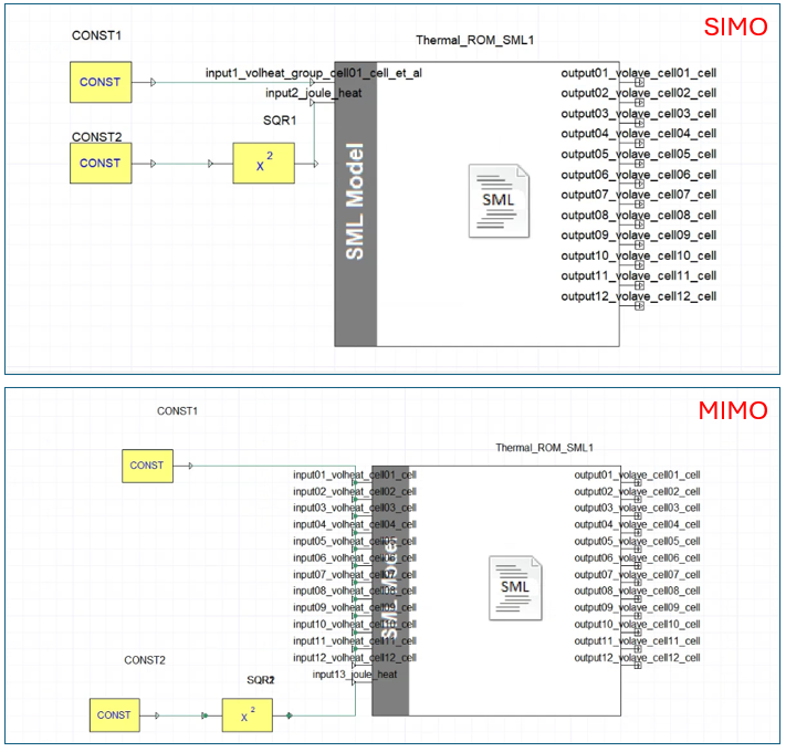
The following image shows the different selection procedures for Single-Input Multiple-Output (SIMO) versus Multiple-Input Multiple-Output (MIMO) ROMs when selecting the Volume Heat. Tip: Specify the wattage Value before clicking the “Add as a Group” or “Add Individually” buttons.
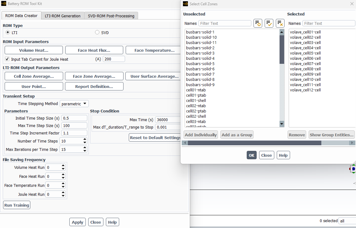
The Input Tab Current for Joule Heat is activated in both cases, and both cases use cells added individually for the Cell Zone Average, as shown below. After setting the Transient Setup, the settings are applied, and Run Training is activated.
Digital Twin Setup in Twin Builder
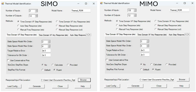
The Digital Twin functionality for Linear Time Invariant ROM in Twin Builder is accessed via Twin Builder > Toolkit > Thermal Model Identification. The images below show the sequence of steps for executing the LTI model with Single Input Multiple Output Reduced Order Model (left) and Multiple Input Multiple Output Reduced Order Model (right) in Twin Builder.
The generated model is dragged from the component library into the schematic window. Constant inputs for heat load and current are added and connected to the model. A square function is added between the current constant block and the joule heat input because heat load is a function of current squared. For the SIMO ROM, a constant heat load corresponds to the module’s head load. For the MIMO ROM, a constant heat load is applied to all inputs and equals the heat load per cell.
Twin Builder analysis is performed to generate the transient temperature results. The simulation calculations are performed to generate the results, with a focus on temperature and simulation time. Fluent runs were performed in parallel with 10 processors, using a time step size equal to the maximum time step size specified for the Digital Twin runs. The treatment data are analyzed to answer theoretical questions and to confirm or refute predictions.
LTI ROM Results: Training Time, Simulation Speed, and Temperature Accuracy
Training Time: SIMO vs MIMO
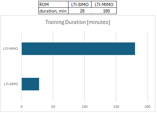
The charts below display the time spent on training the ROMs in Fluent. The Multiple Input Multiple Output (MIMO) took over six times longer than the Single Input Multiple Output (SIMO) training because there were 13 inputs compared to 2.
Simulation Time: Digital Twin vs Full Fluent
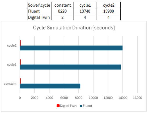
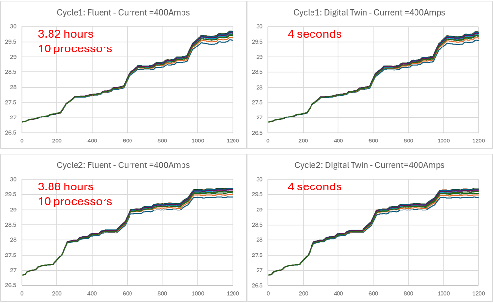
The charts below show the time spent simulating usage in Fluent and Digital Twin. The first scenario had a constant heat load, while the second and third scenarios had transient heat loads. The Digital Twin run times were less than 4 seconds. The corresponding Fluent runs took hours.
Temperature Comparison: Constant Heat Load
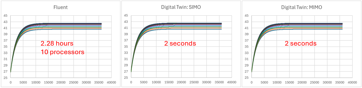
The charts below compare the temperature between the Fluent runs and the corresponding SIMO and MIMO ROMs under a constant heat load. It is very difficult to see a difference in the temperature; however, the difference in simulation time is large.
Temperature Comparison: Transient Cycle Loads
The charts below compare the temperature between the Fluent runs and the corresponding Digital Twin runs under forward- and reverse-cycle loads. It is very difficult to see a difference in the temperature; however, the difference in simulation time is large.
Battery Current Influence on Temperature
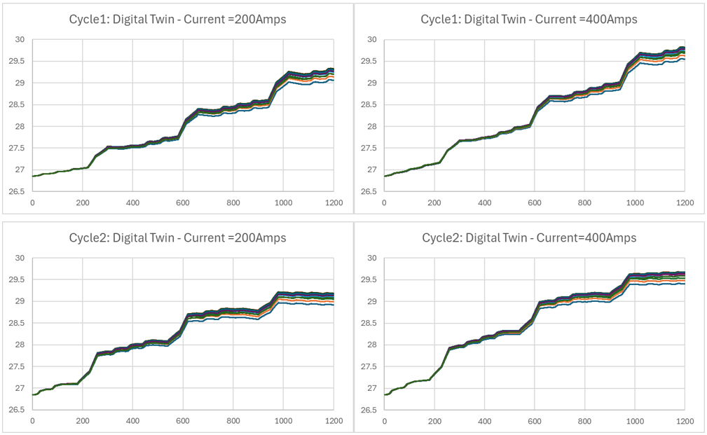
The charts below show the temperature comparison between the two current levels under forward- and reverse-cycle loads. A half-degree difference in temperature is observed at the end of the cycles. Each run took less than 4 seconds to execute.
Video
The following video highlights the setup for both SIMO and MIMO using Fluent and Twin Builder.
Benefits of LTI Reduced Order Models for Battery Thermal Analysis
ANSYS offers advanced capabilities for simulating battery module thermal systems, which offer numerous benefits, including enhanced design optimization, improved reliability, and cost savings. By accurately predicting battery module performance per usage cycles, manufacturers can design products that meet specific requirements more efficiently.
Ultimately, ANSYS Fluent and Digital Twin provide a comprehensive virtual environment for evaluating usage cycles and fine-tuning cooling systems.
Ansys Fluent and Digital Twin enable the evaluation of multiple design/input factors, such as constant or variable heat loads. A battery thermal engineer can evaluate multiple design options in the Digital Twin to understand the thermal behavior in real time. Beyond Digital Twin and Fluent, ANSYS provides tools such as LS-Dyna, DesignXplorer, OptiSLang, and Mechanical for further design parametrization and evaluation.
Building digital twins for battery thermal simulation or comparing ROM approaches? SimuTech Group’s CFD and thermal consulting engineers work with Ansys Fluent, Twin Builder, and the full battery simulation suite. For more on battery ROM workflows, see our article on SVD reduced order models for battery module thermal analysis. Learn more about Ansys Twin Builder or contact us to discuss your project.