Brain Implant Thermal Design Challenges
The Importance of Thermal Management
Designing brain implants poses unique thermal challenges due to the delicate nature of neural tissue and the brain’s limited heat-dissipation capacity.
Small increases in temperature caused by brain implants—just 1–2°C above baseline—can lead to irreversible cellular damage or impair normal brain function. The problem is exacerbated by the constant operation of microelectronic components within the implant, which generate heat in an environment where natural cooling mechanisms like blood flow and convection are limited. Moreover, implant miniaturization further concentrates heat in smaller volumes, increasing the risk of localized thermal hotspots. As regulatory bodies impose strict limits on temperature rise (typically not exceeding 1°C), thermal management becomes not just an engineering hurdle but a fundamental safety and viability concern in implant design.
Engineering Solutions for Brain Implant Cooling
To manage heat in brain implants, engineers employ a combination of material science, structural design, and energy-efficient electronics. Low-power integrated circuits (ICs) are essential, often leveraging advanced Complementary Metal-Oxide-Semiconductor (CMOS) technologies to minimize heat generation. Thermally conductive but biocompatible materials, such as diamond-like carbon or ceramics, are used to help spread and dissipate heat across larger surfaces. Passive cooling structures—such as microchannels and heat spreaders—are integrated into the implant architecture to facilitate heat transfer away from sensitive tissue. In some cases, intermittent operation or duty cycling is employed to allow tissues to cool between bursts of activity. These solutions must strike a delicate balance between performance, safety, and biological compatibility, often necessitating iterative testing and refinement throughout the design process.
Using Ansys Fluent to Evaluate Thermal Performance
Ansys Fluent plays a critical role in evaluating and optimizing the thermal performance of brain implant designs. Engineers use it to simulate heat generation and dissipation within complex geometries, accounting for conduction through materials, convection with surrounding tissue, and metabolic heat from the brain itself. Fluent’s ability to model multi-physics environments enables detailed investigation of implant-tissue interaction under various physiological scenarios. By defining boundary conditions that mimic cerebral blood flow and ambient neural conditions, engineers can assess how design choices—such as material selection or component layout—impact localized temperature rises. This helps identify hotspots and test thermal mitigation strategies virtually, significantly reducing the need for costly and time-consuming in vivo experiments in early development stages.
Simulation Method and Setup
Setting up a brain implant thermal simulation in Ansys Fluent involves several steps. These steps include the thought map, product map, and Fluent case setup.
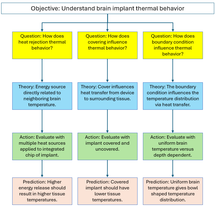
Thought Map
A thought map of modeling characteristics is generated to organize and represent ideas, concepts, or information in a structured way. The thought map below shows the simulation study’s objective and the questions asked to address it. Each question is followed by a theory, an action, and a prediction. Results would also be added to the bottom of each branch as they are generated.
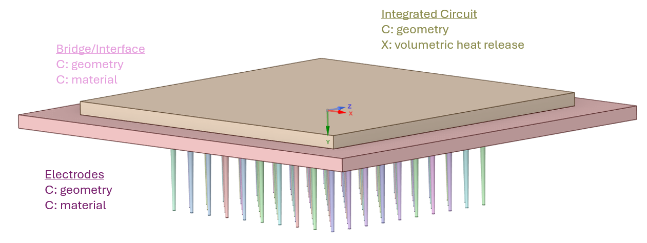
Product Maps
A product map of the implant and surrounding brain is generated to list and categorize product features. A product map indicates some factors that correspond to theories/actions in the thought map. The image below shows a map of the implant device.
The image below shows a map for the remaining computational domain which includes a cylinder of 150mm and depth of 50mm.
Fluent Simulation Mesh
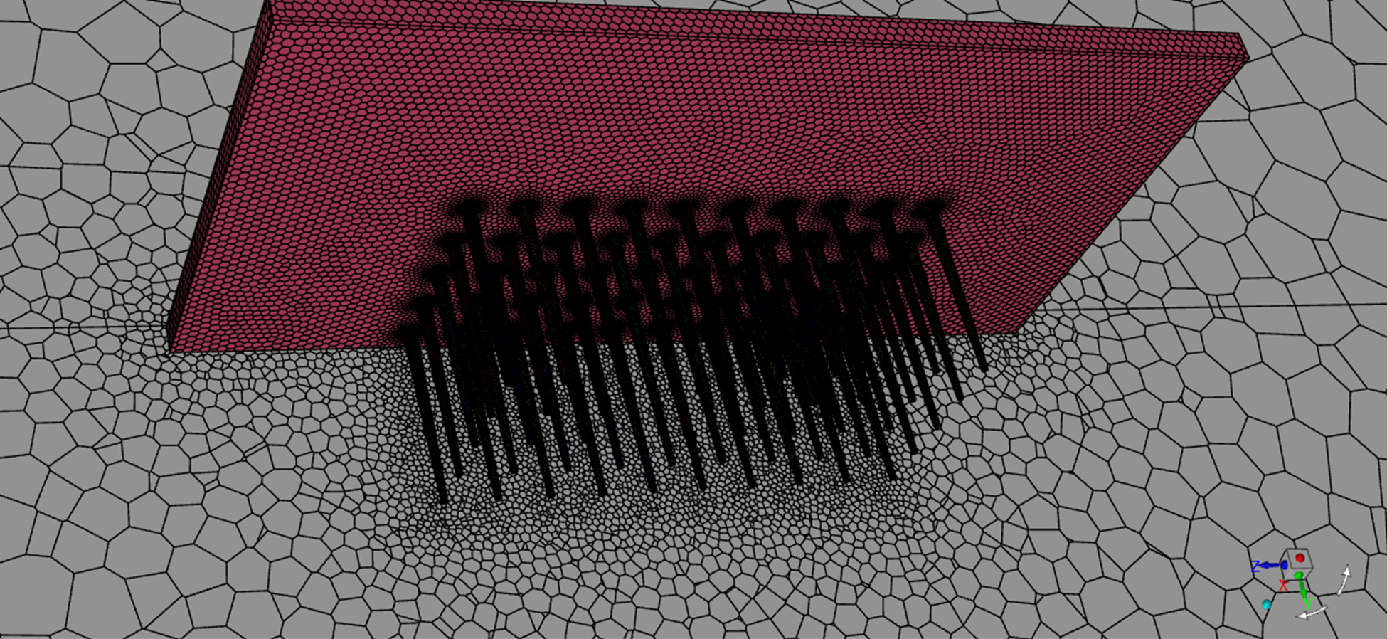
The simulation domain contains features spanning a wide range of length scales. The brain domain has a diameter of 150mm; however, the implant device contains electrodes with dimensions on the order of a few microns. It was found that the mesh should be generated in two stages: one focuses only on the implant device and the surrounding zone, and the second includes the remaining domain. The two-volume meshes are joined together in Fluent using the Domain > Zones > Append > Append Case File feature.
The mesh image below shows a vertical section view through the center of the complete model domain.

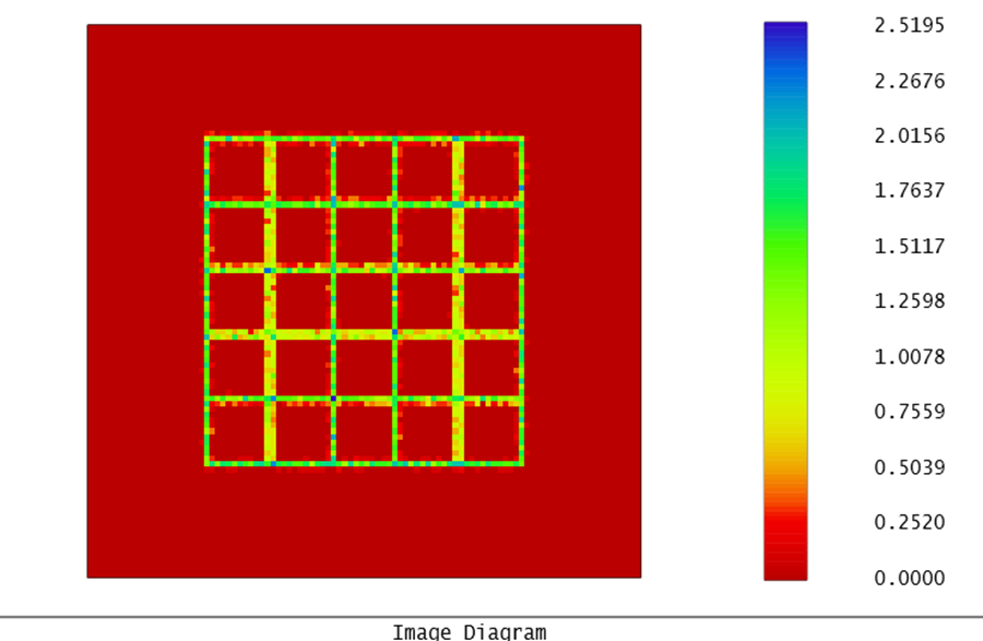
The mesh image below shows a surface mesh plot of the bridge/interface along with the electrodes.
Fluent Simulation Setup
Fluent models are set up to address the questions and geometry addressed by the thought map and the product map. Steady-state calculations are performed.
Physics Models: The Energy equation is activated. Viscosity is set to Laminar. All other physics models are deactivated.
Materials: The following image shows the material specification. Density and thermal conductivity are key material properties.
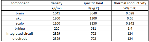
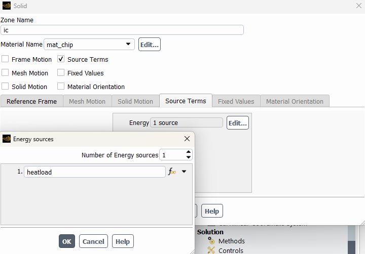
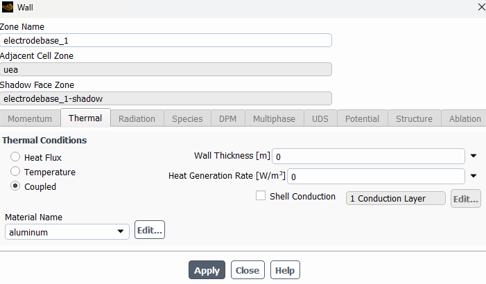
Cell Zone – Boundary Conditions: Materials are assigned to the corresponding cell zones. Default options are used for all cell zones except for the integrated circuit. For the integrated circuit, the source term is activated, and a volumetric heat source is applied.
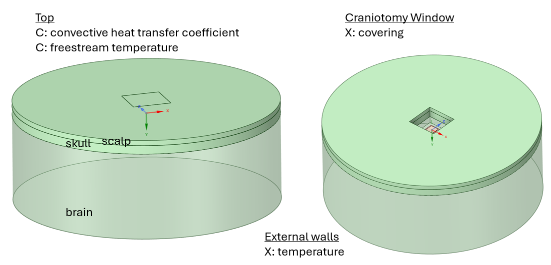
Face Zone – Boundary Conditions: Coupled heat transfer wall boundary conditions are applied at solid-solid interfaces. Shell conduction could be activated to account for thin coatings, if needed.
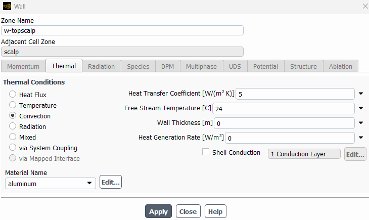
Convective boundary conditions are used for the surface(s) at the top exposed to air. Convective heat transfer coefficient and free stream temperature are assigned.
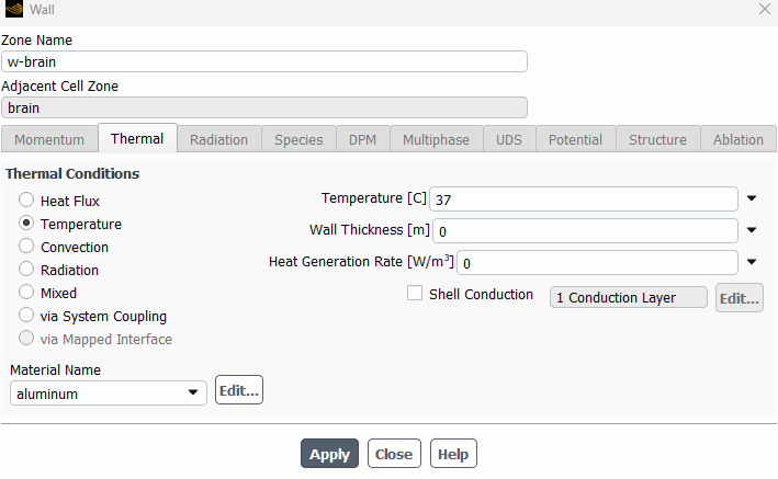
The bottom and cylindrical sides of the brain are specified at a fixed temperature. An expression-based temperature could be specified based on the soak temperature along a vertical line through the center of the computational domain.
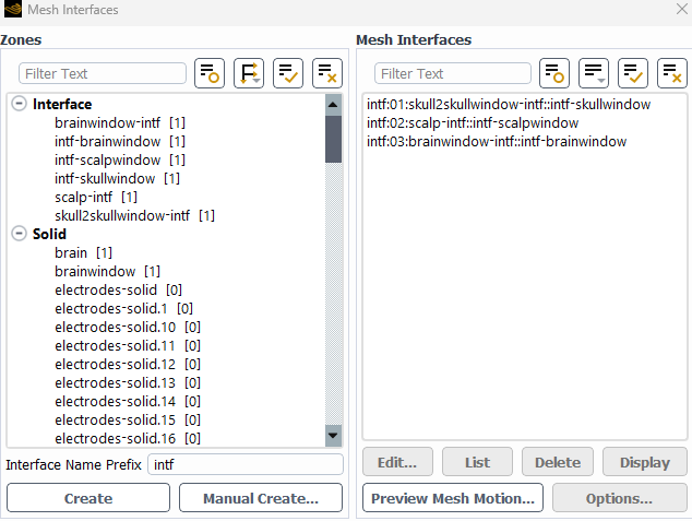
Mesh interfaces: Mesh interface zones are generated where the core mesh interfaces with the brain/skull mesh.
Methods: SIMPLE pressure-velocity coupling is used with Second Order Upwind Energy Spatial Discretization. An under-relaxation factor of 1.0 is used for Energy. A residual convergence target of 1e-15 is used.
Monitors: Surface facet maximum temperature reports are generated at implant device surfaces that touch brain or skull tissue to monitor those temperatures as a function of iteration number.
Fluent Simulation Results
Maximum Temperature Plots
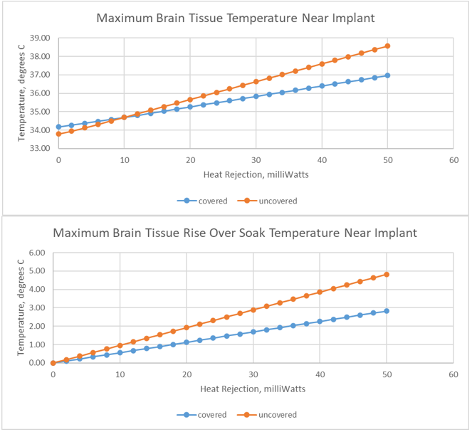
The first chart below shows the relationship between the maximum temperature experienced in brain or skull tissue next to the brain implant as a function of heat load. The relationship is very close to linear for both covered and uncovered implant devices. The slope for the uncovered scenario is higher than the slope for the covered scenario. The maximum temperature is higher for the covered implant when the device heat load is zero.
The second chart shows the same data relative to the soak temperature at zero heat load. This chart is helpful for identifying the allowable heat load per a required maximum temperature rise, such as 1 and/or 2 degrees C.
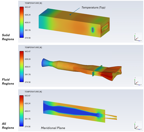
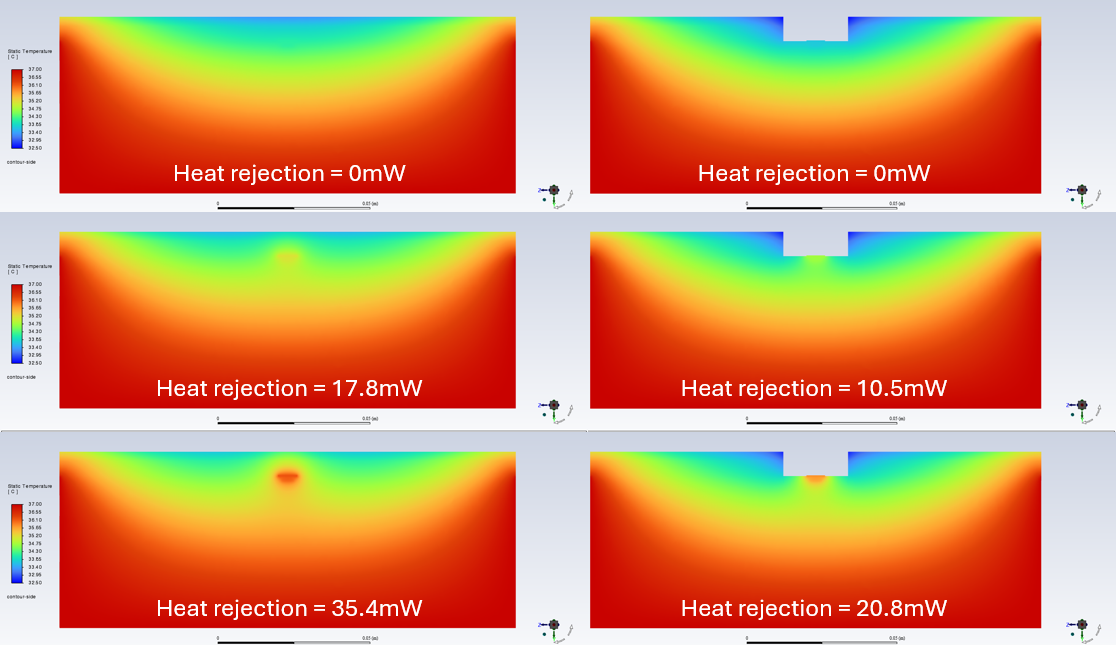
Temperature Contours
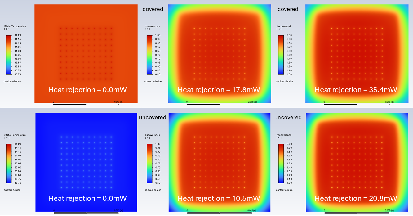
The contour plots below show the raw temperature distribution on a vertical section through the domain. Three heat loads are displayed for each covering/uncovering scenario. The heat loads correspond with soak, 1 degree C rise, and 2 degree C rise.
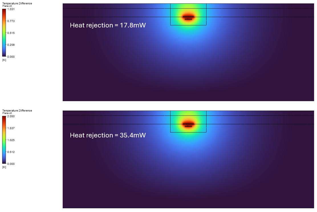
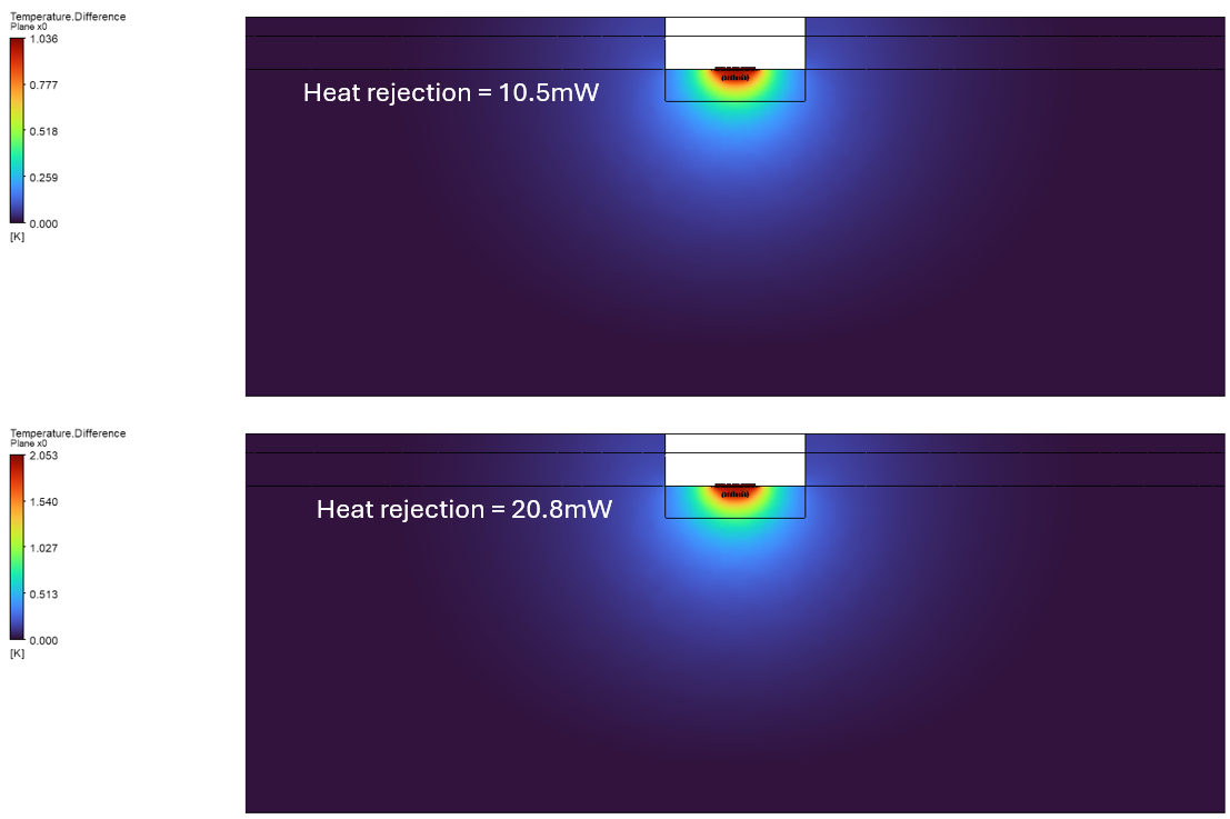
The following images show the temperature difference between a specified heat load and the zero-soak heat load. These images directly display the impact of the powered device implant on the nearby tissue.
Implant Device Surface Temperature
The image below shows the surface temperature distribution on the brain side of the implant device for the specified heat loads, corresponding to temperature rises of 1 and 2 degrees C. The image also shows the higher temperature of the covered implant device when a zero heat load is used.
References:
S. Kim, P. Tathireddy, R. Normann, and F. Solzbacher, “Thermal Impact of an Active 3-D Microelectrode
Array Implanted in the Brain,” IEEE Transactions on Neural Systems and Rehabilitation Engineering, Vol. 15, No. 4, December 2007.
Ansys Solution Benefits
Ansys offers advanced capabilities for simulating brain implant devices, which offer numerous benefits, including enhanced design optimization, improved reliability, and cost savings. By accurately predicting thermal performance, manufacturers can design products that meet specific requirements more efficiently.
Ultimately, Ansys Fluent provides a comprehensive virtual environment to evaluate the brain implant device temperature.
Ansys Fluent enables the evaluation of multiple design/input factors such as heat load, covering, and domain boundary conditions. A design engineer can evaluate multiple design options to understand the temperature behavior. Beyond Fluent, ANSYS provides tools such as CFX, LS-Dyna, DesignXplorer, OptiSLang, and Mechanical for further design parametrization and evaluation.
Working on thermal simulation for medical devices or implants? SimuTech Group has deep expertise in healthcare and biomedical simulation consulting, including CFD-based thermal analysis of implantable devices. For more on our thermal CFD capabilities, see our thermal analysis simulation services. Contact us to discuss your project.