Thermoforming simulation in Ansys Fluent Polyflow allows engineers to evaluate material behavior, thickness distribution, and mold interaction before physical prototyping. This blog walks through a complete thermoforming simulation setup and compares shell versus volume mesh element results in terms of accuracy, memory usage, and CPU time.
Design Challenges in Thermoforming Simulation
Thermoforming presents several design challenges, primarily due to the material’s behavior during heating and molding.
-
- Uneven material stretch: When plastic is heated, it becomes soft and malleable, but this can lead to uneven stretching during forming, causing variations in thickness and strength. Designers must account for uniformity in material flow to avoid weak spots or excess material that can lead to warping or excess scrap.
- Tooling complexity: The molds must be precise and well-designed, as imperfections can result in surface defects or poor part fit. The design must also accommodate draft angles — slight tilts on mold surfaces that allow parts to release easily — but this can limit design freedom, especially for parts with intricate geometries.
- Thermal control: Parts must be uniformly heated, and maintaining consistent temperatures across the material can be difficult, especially with thicker parts.
- Post-processing requirements: Trimming and edge cleanup after forming can add to production time and cost.
Overall, thermoforming requires careful planning, material selection, and mold design to ensure quality and efficiency.
Engineering Strategies for Thermoforming Process Improvement
To address thermoforming challenges, engineers employ several strategies:
- Material selection: Choosing the right thermoplastic with consistent flow properties and the ability to maintain uniform thickness during forming helps prevent stretch issues.
- Tooling precision: Molds are designed with tolerances that account for material shrinkage and expansion during heating.
- Multi-zone heating: Using multi-zone heating systems ensures consistent temperature distribution, reducing the risk of uneven forming.
- Cooling channel design: Molds with adjustable cooling channels help maintain uniform cooling rates, preventing distortion after forming.
- Draft angle balancing: Engineers carefully balance ease of part removal with design aesthetics by integrating slight angles into the mold, minimizing impact on intricate shapes.
- Complex geometry solutions: For parts with complex geometries, engineers may use multi-part molds or vacuum-assist technologies to improve material flow and avoid stretching in critical areas.
These solutions combine to improve both design and manufacturing efficiency.
Why Ansys Fluent Polyflow Is Built for Thermoforming Simulation
Ansys Fluent Workspace Polyflow provides a powerful simulation environment for evaluating thermoforming solutions. It combines computational fluid dynamics (CFD) with material flow analysis, allowing engineers to model how thermoplastics behave under heat and pressure during the forming process. Using Polyflow, engineers can simulate material flow patterns, temperature distributions, and stretching effects, helping identify potential issues such as thinning or uneven heating before physical prototyping.
The software enables precise thermal management simulations, allowing engineers to adjust and optimize the multi-zone heating systems for consistent temperature control across the material. It also aids in fine-tuning mold design by predicting the material’s behavior at different stages, helping prevent defects like warping or incomplete forming. By integrating material properties such as viscosity and elasticity, Polyflow predicts material flow through complex geometries and helps optimize draft angles to ensure ease of part release without compromising design integrity. Engineers can also assess the performance of vacuum-assist systems and fine-tune cooling channels for optimal post-forming shape retention. This comprehensive approach allows engineers to evaluate and improve thermoforming processes digitally, enhancing efficiency and quality.
Simulation Setup: Thought Map, Product Map, and Polyflow Configuration
Setting up a thermoforming simulation with Ansys Fluent Workspace Polyflow involves several steps. These steps include the thought map, product map, and Polyflow case setup.
Thought Map
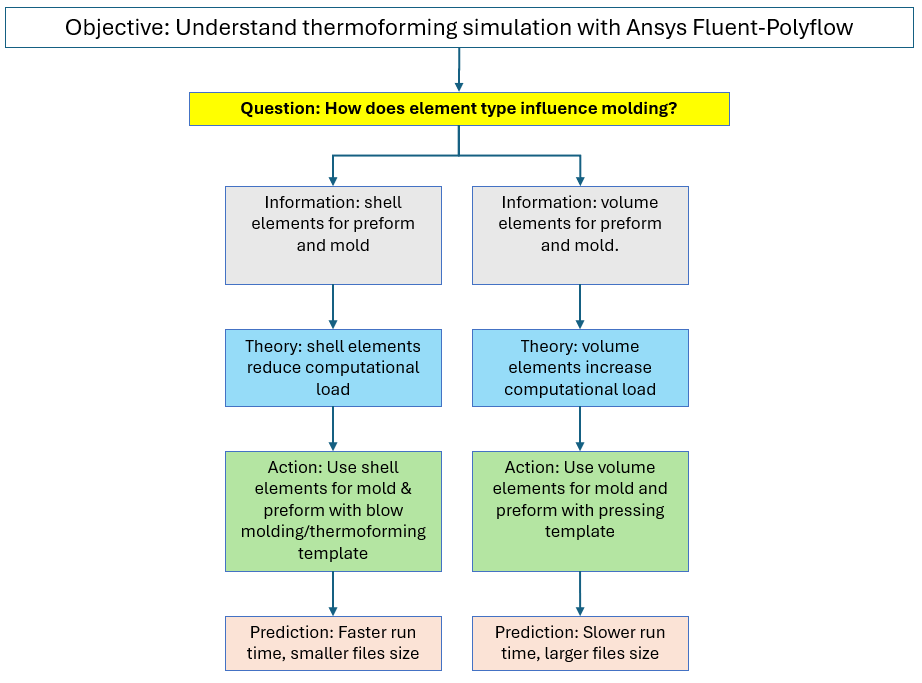
A thought map of thermoforming characteristics is generated to organize and represent ideas, concepts, or information in a structured way. The thought map below shows the simulation study’s objective and the questions asked to address it. Each question is followed by a theory, an action, and a prediction. Results would also be added to the bottom of each branch as they are generated.
Product Map
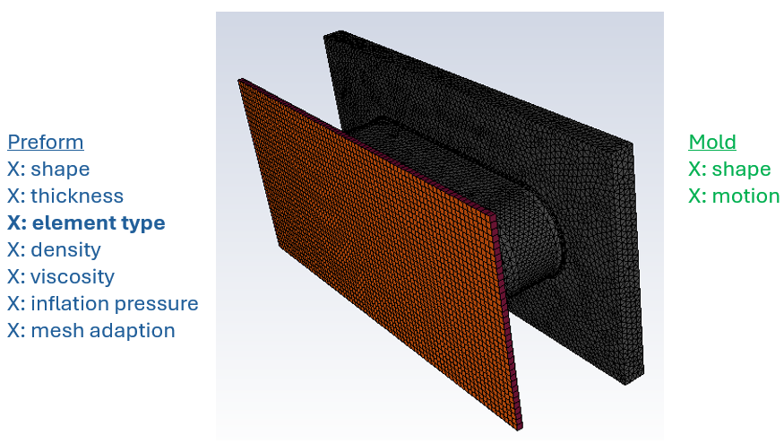
A product map of the thermoforming preform and mold is generated to list and categorize product features. A product map indicates factors that correspond to theories/actions in the thought map.
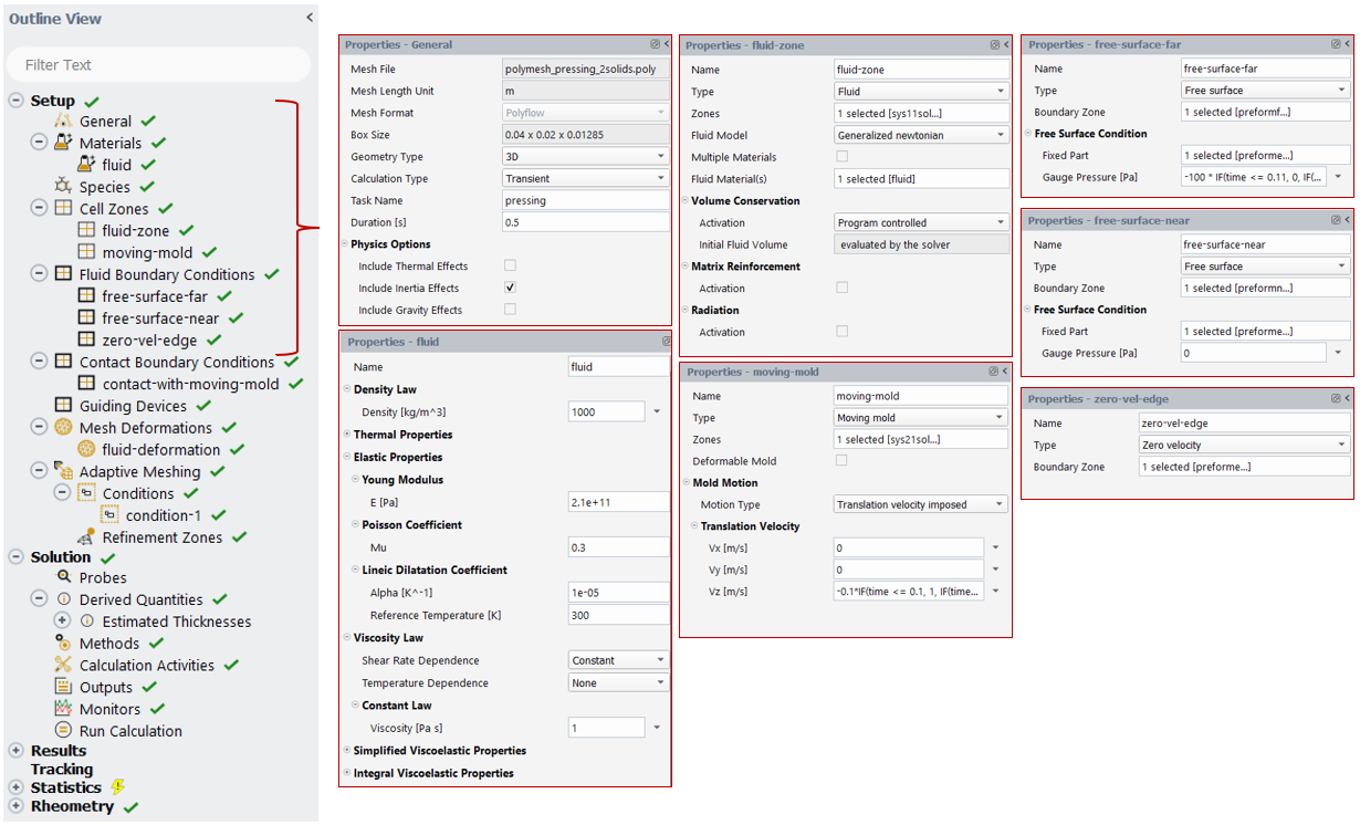
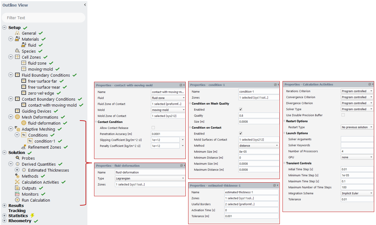
Polyflow Simulation
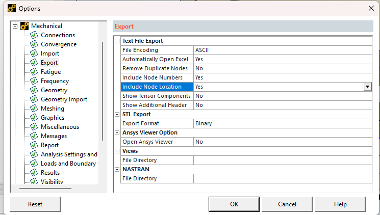
Polyflow models are generated per the studies produced by the thought map. In this case, a one-factor, two-level study is employed, yielding two distinct Polyflow treatments. The images below show the sequence of steps for populating inputs for a Polyflow model.
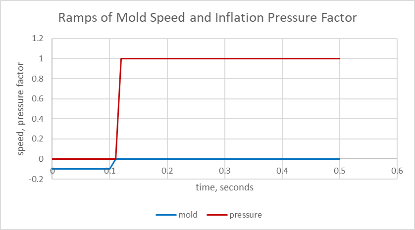
The chart below shows the transient mold motion and the inflation pressure factor.
The simulation calculations are executed to generate the results. Treatments are analyzed to answer the theory questions and confirm or contradict predictions.
Thermoforming Simulation Results: Shell vs Volume Elements in Polyflow
Graphical Analysis
Below is an animation of the preform thickness result using shell mesh elements.
{% video_player “embed_player” overrideable=False, type=’hsvideo2′, hide_playlist=True, viral_sharing=False, embed_button=False, autoplay=False, hidden_controls=False, loop=False, muted=False, full_width=False, width=’908′, height=’544′, player_id=’190085499739′, style=” %}
Below is an animation of the preform thickness result with volume mesh elements.
{% video_player “embed_player” overrideable=False, type=’hsvideo2′, hide_playlist=True, viral_sharing=False, embed_button=False, autoplay=False, hidden_controls=False, loop=False, muted=False, full_width=False, width=’908′, height=’624′, player_id=’190081378610′, style=” %}
These animations show a similar thickness result between the shell and volume element meshes.
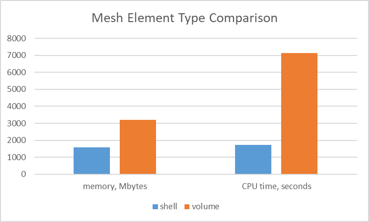
The chart below illustrates the difference between the simulations in terms of memory usage and CPU time. Use of volume elements consumes twice as much memory and consumes 4 times as much CPU time.
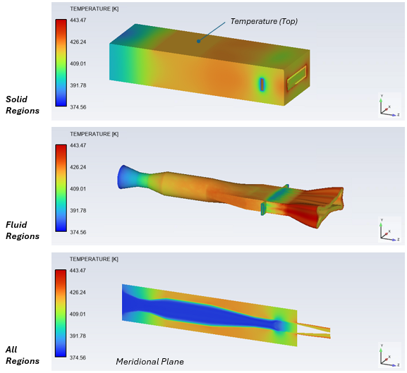
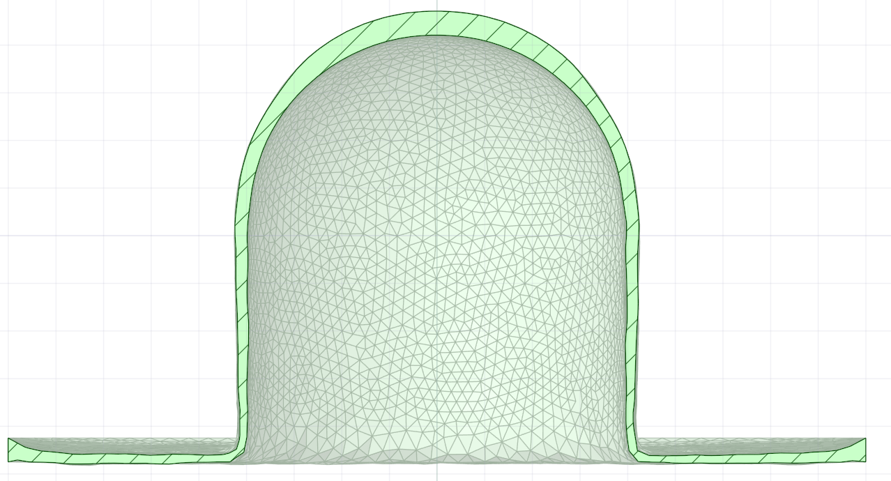
A benefit of using volume elements that may outweigh the memory and time is that one may output the geometry of the final deformed shape in .stl format. This geometry can be used for further analysis, such as structural analysis. The image below shows a section view of the final shape.
Video
The following video highlights the setup.
Benefits of Ansys Fluent Polyflow for Thermoforming Process Design
ANSYS offers advanced capabilities for simulating thermoforming, which offer numerous benefits, including enhanced design optimization, improved reliability, and cost savings. By accurately predicting thermoforming performance, manufacturers can design products that meet specific requirements more efficiently.
Ultimately, ANSYS Fluent Polyflow provides a comprehensive virtual environment for fine-tuning material behavior, mold design, and process parameters, leading to more efficient production, reduced trial-and-error, and improved part quality in thermoforming processes.
Ansys Fluent Polyflow enables the evaluation of simulation factors such as the shell or volume element. A manufacturing engineer can evaluate multiple design options to understand the molding behavior. Beyond Polyflow, ANSYS provides tools such as LS-Dyna, DesignXplorer, OptiSLang, and Mechanical for further design parametrization and evaluation.
Working on thermoforming, blow molding, or polymer processing simulation? SimuTech Group’s CFD consulting engineers use Ansys Fluent, Polyflow, and the full material processing simulation suite. For more on Polyflow capabilities, see our article on Ansys FreeFlow and EnSight for visualizing heat transfer in a stirred tank. Learn more about Ansys Fluent or contact us to discuss your project.