Thermal Contact Conductance | Setup with Ease in Ansys Mechanical
Ansys Mechanical (Workbench) makes it relatively easy to set up contact pairs. Manual tweaking of contact pair details can improve contact element performance, and the accuracy of results. This document considers some effects of contact pair settings on thermal results. Imperfection in thermal contact behavior can be inspected in plots of thermal flux in directions perpendicular to the contact elements.
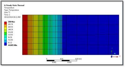
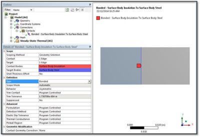
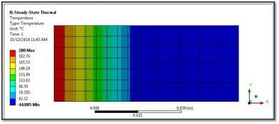
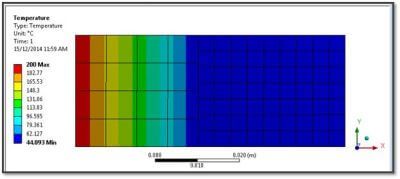
A series of tests were done on contact between two 2D blocks in contact. Low-order quad-shaped 2D thermal elements were employed. One block is a thermal insulator, and the other is a thermal conductor. In Figure 1 above, a temperature boundary condition of 200C is applied to the left end of the model at a thermal insulator in a two-block model. A convective load is placed on the right end at a thermal conductor, with convection coefficient h=50W/m2 and an ambient temperature of 22C. Thermal results are affected by settings for the contact pair between the two blocks.
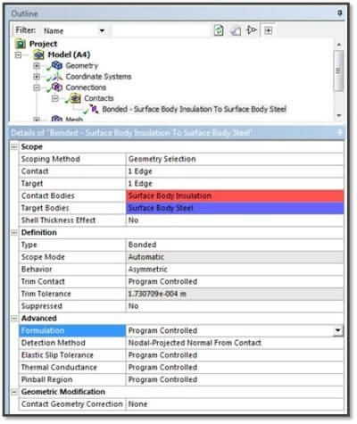
In the present set of tests, apparently best results can be seen if the Details for the contact pair have “Detection Method” set to the non-default value of “Nodal–Projected Normal from Contact”. Results can be better if the Contact side in a contact pair is on the body with the lower thermal conductivity, and with a finer mesh.
Using Thermal Contact in Workbench Mechanical – Five Tests
Workbench Mechanical offers a variety of settings for a contact pair. Some settings are more relevant to structural contact than to thermal contact, but some are important for thermal results as well. At any contact pair, the mesh could be finer on one side of the contact pair than the other. The thermal conductivity can differ in the materials on the two sides of a contact pair. Contacts could be set to symmetric or asymmetric, and with asymmetric pairs, the contact could be on the side with the higher or with the lower thermal conductivity.
Five models were run. They considered an asymmetric thermal contact pair with variations in Details settings:
- Finer mesh on the insulator, contact side on the insulator.
- Finer mesh on the insulator, contact side on the conductor.
- Finer mesh on the conductor, contact side on the insulator.
- Finer mesh on the conductor, contact side on the conductor.
- Finer mesh on the insulator, contact on the insulator, “Nodal—Projected Normal from Contact”.
Four tests were done with Bonded contact, and Program Controlled Advanced settings. This means that thermal contact conductance is very high, and in the first four tests, the Detection Method will use contact at “Gauss Point”. All of these settings caused some irregularity in thermal flux perpendicular to the contact pair (in the X direction). Setting (1) above, “Finer mesh on the insulator, contact side on the insulator,” caused the least flux variation.
The fifth case was run with Detection Method set to “Nodal—Projected Normal from Contact”. A much more even thermal flux resulted at the contact pair, plus less sensitivity to assignment of contact, target, and mesh density.
Modeling Thermal Contact Resistance
Thermal Conductivity: Case 1:
A first model was run with Contact and finer meshing in the low thermal conductivity thermal insulator body on the left side of the model. The body on the right is a thermal conductor.
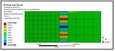
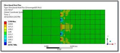
In the thermal flux plots, “Unaveraged” is used to highlight uneven results.
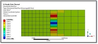
In the figure above, note slight unevenness in the Flux X values on the target side (thermal conductor) of the model.
Thermal Conductivity: Case 2:
A second model placed the Contact on the conductor on the right side of the model.
In the second figure above, note that the thermal flux values have a greater variation than in the model with Contact on the Insulator side of the model.
Thermal Conductivity: Case 3:
A third model placed the fine mesh in the conductor on the right, and the Contact side on the insulator on the left.
In the second figure above, note that the thermal flux values have a even greater variation than in previous setups.
Thermal Conductivity: Case 4:
A fourth model placed the Contact and the finer mesh on the conductor on the right side of the model.
In the second figure above, the thermal flux values have wider variation than in the case with a finer mesh in the insulator, and the Contact edge on the insulator side of the contact.
Thermal Conductivity: Case 5:
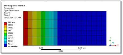
In Model 5, the Contact is on the insulator. The insulator is given a finer mesh. The Detection Method is set to “Nodal—Projected Normal from Contact”. This results in an even flux distribution on the contact pair’s Target side.

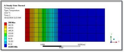
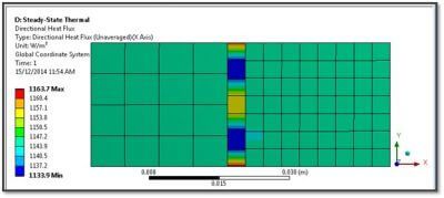
The temperature distribution and flux in X in the Case 5 study are as shown below.
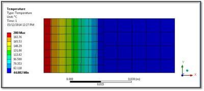
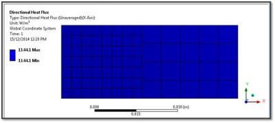
As can be seen in the second figure above, the thermal flux takes on an even distribution once the contact pair is set to “Nodal—Projected Normal from Contact”. This also is seen when the contact pair is reversed, with the Contact on the conductor body in the model. However, since higher thermal gradients will be found in the insulator in such a model, the finer mesh and contact would in general be placed on the insulator side of such a contact pair.
Conclusions | Thermal Contact Configuration
Workbench Mechanical offers several settings for contact pairs in thermal models. To achieve good representation of temperatures and thermal flux values, it may be advisable to place the Contact side of a thermal contact on the body with a lower thermal conductivity value, as well as using finer meshing on the body with lower thermal conductivity. Smoother thermal flux distribution has been observed with the contact pair set to:
“Nodal—Projected Normal from Contact”
Measured Thermal Contact Conductance (TCC) Versus Load Data
Users will want to consider these observations when running thermal models that have thermal contact, and for analyzing thermal contact behavior. Click HERE for configuring thermal contact at joints in Mechanical Workbench. Click HERE for heat conduction across a contact element gap in Mechanical Workbench.