Heat Conduction Across a Contact Element Gap | Ansys Mechanical Workbench
Heat Transfer Multiphysics Modeling & Thermal Contact Conductance (TCC)
Thermal models, whether single-field thermal analysis or direct-coupled multiphysics models such as with structural and thermal degrees of freedom, heat can be transferred across a gap between two bodies if a contact pair has been created on the two faces of the gap, as a function of gap size. This article will review this relationship in greater detail and illustrate how to employ the appropriate Thermal Contact Conductance (TCC) settings.
 The keys to setting up such a model are:
- Create a Table Array that has GAP as a primary variable
- Set up values for thermal contact conductance as a function of gap sizes ranging from zero (contact) up to the pinball radius
- Supply the name of the Table Array as Real Constant 14 for the contact elements
Gap Size, Pinball Radius & Heat Transfer
The gap must be smaller than the pinball radius for any heat to be transferred. Gap values are entered with minus signs, so the Table Array can go from the negative of the pinball radius up to zero for contact, or even positive if penetration is expected.
This article illustrates such a modeling method, applied in Workbench Mechanical via an APDL Commands Object. The technique is also applicable in Ansys Mechanical APDL.
Ansys Help System Comments | Heat Conduction
The possibility of supplying Real Constants as table arrays is discussed in the Ansys documentation, for example:
- 3.9.1.2. Defining Real Constants in Tabular Format
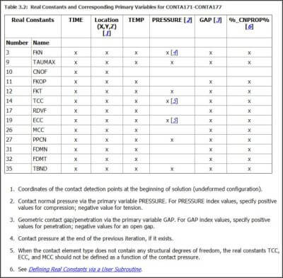
- For certain real constants, you can define the real constant as a function of primary variables by using tabular input. Table 3.2: Real Constants and Corresponding Primary Variables for CONTA171-CONTA177 lists real constants that allow tabular input and their associated primary variables.
Note the requirement for the gap values to be expressed with minus signs:
- Geometric contact gap/penetration (GAP); specify positive index values for penetration, negative index values for an open gap.
As usual in Ansys, the Table Array references as the argument of a command are done by placing the name of the Table Array inside a pair of percent signs “%”:
- When defining real constants via the R, RMORE, or RMODIF command, enclose the table name in % signs (i.e., %tabname%).
An example of creating a Table Array and supplying values is illustrated by these commands:
*DIM,my_h,TABLE,2,,,GAP ! Primary variable on row is GAP
my_h(1,0)=-2.0 ! When gap is open this amount
my_h(2,0)= 0.0 ! When gap is closed
my_h(1,1)=0.0 ! TCC when gap is open above amount
my_h(2,1)=2.0 ! TCC when gap is closed
A Contact Conductance of Zero
Note that this example of a 1-dimensional Table Array has only two rows, so it will suggest a linear variation of contact conductance as a function of gap size. This example has gap sizes ranging from -2 distance units (a gap of 2 units), to Zero distance units (when the gap closes). The contact conductance in this example will be zero when the gap reaches 2 distance units, and reach 2.0 when the gap closes.
The following table from the Ansys Help system shows Real Constants that can be represented by Table Array values for contact elements. Note the various primary variables in the column headings. APDL commands are required to implement these for chosen contact pairs:
Thermal Contact Conductance (TCC) in Ansys WB
In the present application, we are interested in GAP and its use in setting TCC, the Thermal Contact Conductance. The Real Constant items that can be applied by using Table Arrays as mentioned the in the list above are:
- FKN= Normal penalty stiffness factor
- TAUMAX = Maximum friction stress
- CNOF = Contact surface offset
- FKOP = Contact opening stiffness
- FKT = Tangent penalty stiffness factor
- TCC = thermal contact conductance
- RDVF = Radiation view factor
- ECC = Electric contact conductance
- MCC = Magnetic contact permeance
- PPCN = Pressure penetration criterion
- FDMN = Normal stabilization damping factor
- FDMT = Tangential stabilization damping factor
- TBND = Critical bonding temperature
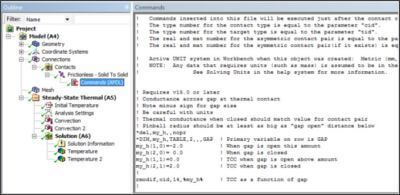
A contact pair that will have heat transfer across a gap has to be a nonlinear contact type that can open. The following example uses Frictionless contact. The other nonlinear contact settings are Frictional and Rough. The example APDL commands are entered in a Commands Object as illustrated below:
Non-Intuitive Units
The following commands are found in the above Commands Object. Note that the units employed are millimeters in this example. This must be the set of units employed when the model is solved. Note that the units for energy in Workbench Mechanical are most easily set when using SI units. Otherwise, energy is in non-intuitive units like Newton-millimeters, or whatever force-displacement units are in use for a model at solution time, unlike the material properties.
! Requires v15.0 or later
! Conductance across gap at thermal contact
Figure 2: Contact Real Constants that Permit Values from Table Array Inputs
! Note minus sign for gap size
! Be careful with units
! Thermal conductance when closed should match value for contact pair
! Pinball radius should be at least as big as “gap open” distance below
*del,my_h,,nopr
*DIM,my_h,TABLE,2,,,GAP ! Primary variable on row is GAP
my_h(1,0)=-2.0 ! When gap is open this amount
my_h(2,0)= 0.0 ! When gap is closed
my_h(1,1)=0.0 ! TCC when gap is open above amount
my_h(2,1)=2.0 ! TCC when gap is closed
!
rmodif,cid,14,%my_h% ! TCC as a function of gap
Heat Transfer and Radius Values in Ansys
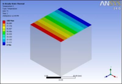
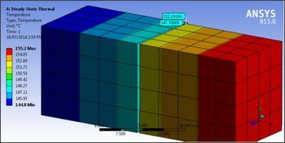
Other details for the Frictionless contact example are shown below. In this example, the gap already exists in the geometry. Note that the pinball radius is larger than the gap, and has been set to a radius value that matches the extreme value in the Table Array above. The pinball could be larger, for this example Table Array reaches zero, stopping heat transfer for larger gap sizes.
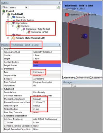
In the above example, the Thermal Conductance Value appears to have been set to match the value in the Table Array. However, because the model is run in millimeter units, the value used in the Ansys Batch job will be internally converted to another power unit (Newton-millimeters per second). The value entered in the Details above will be ignored, because the Real Constant entry for TCC is replaced by the APDL Commands Object.
Conclusions | Thermal Contact Conductance (TCC)
At Ansys version 14.5, it has become possible to have thermal contact conductance across a small gap at a contact pair. Users can define the conductance as a function of gap size, using a table array with GAP as a primary variable. The gap size has to be smaller than the pinball radius, so users should in general set the pinball radius manually when setting up such behavior.
This gap conductance at contact pairs can be added to Workbench Mechanical models by placing an APDL commands object at the nonlinear contact pair of interest.
Users have to be very careful with energy units in APDL Commands Objects in Workbench Mechanical, particularly when solutions are not done in SI units.
The present article has illustrated creation of such an APDL commands sequence. The technique can be used in Mechanical APDL or in Workbench Mechanical models.
- For guidance on Ansys Post-Processing
- For Support on performing ‘EKILL‘ in Workbench
- APDL Command Objects post-Spectral Analysis
- For Separating DB Database Files from RST Files
- Measuring Geometric Rotation in Mechanical WB
- CAD Geometry Deformation Plasticity