Why Welds Fail When Everything “Looked Fine”
Welds concentrate stress, alter microstructure, and lock in residual stresses that shift how a structure actually carries load. Add variable-amplitude service conditions, like start/stop cycles, vibration, or thermal swings, and a joint that passes a static check can still crack early in life. To fix, you need a disciplined fatigue workflow that connects material behavior, joint geometry, loading spectra, and verification.
This article distills proven practices SimuTech Group uses in weld fatigue design and fracture simulations to make welded structures more durable, easier to maintain, and less costly to warranty.
In Weld Fatigue Design, Always Start With The Right Model
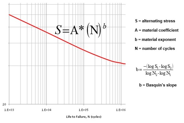
S-N (stress-life) for high-cycle fatigue and weld classifications
- Use when elastic stresses dominate and cycles are high.
- For welded details, base life on weld class/detail category S-N curves (e.g., toe, root, transverse attachment) rather than base-metal properties.
- Local notch effects are implicitly covered by the detail category approach when using structural/hot-spot stress.
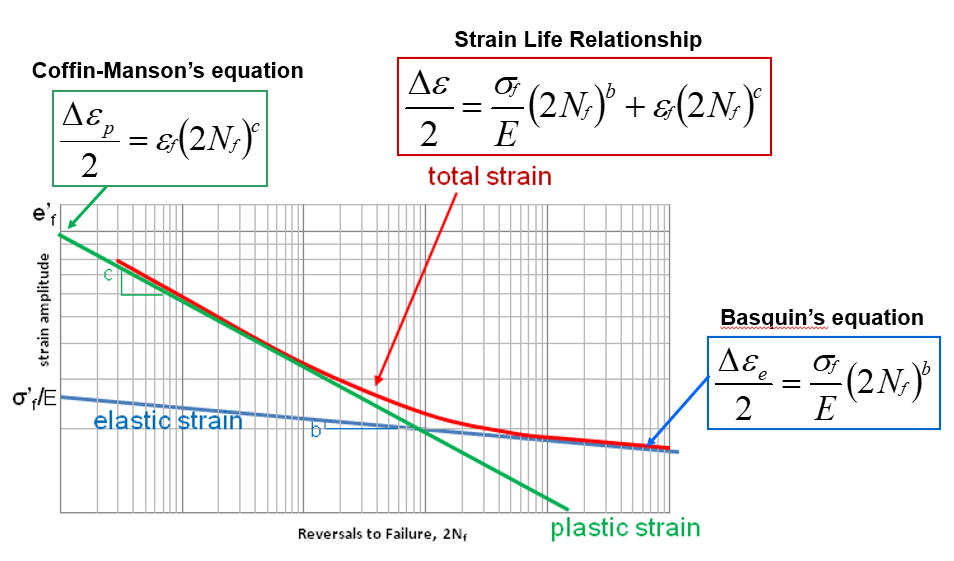
ε-N (strain-life) for low-cycle fatigue and local plasticity
- Use when you expect localized yielding (fit-ups, start/stop regions, thermal transients).
- Captures crack initiation well; often paired with a crack growth model for total life.
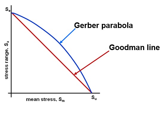
Mean stress corrections
- Real joints rarely see zero-mean loading.
- Apply Goodman or Gerber corrections (or Smith-Watson-Topper for ε-N) when tensile mean stress or residual stress biases the cycle.
- Residual tensile stress near the toe can be significant after welding.
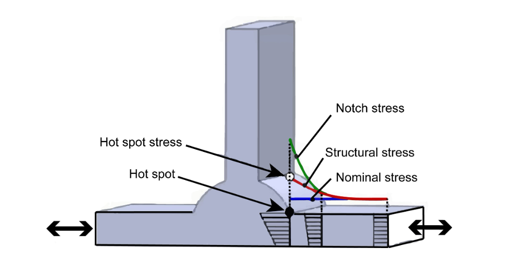
Choose A Stress Definition That Matches Your Method
Different weld fatigue design methods are calibrated for different stress inputs. Mixing these inputs in one analysis can lead to overly optimistic life predictions.
| Method | Stress input | Where it comes from | Notes |
| Detail-category S-N | Structural/hot-spot stress | Extrapolated surface stress near the weld toe | Do not use highly localized notch stress here |
| Notch-based S-N/ε-N | Local notch stress/strain | Fine mesh at the weld toe or root | Requires realistic Kt and mesh convergence |
| Weld throat (fillet) | Throat stress | Based on weld size and load path | Useful for simple fillets under static + screening fatigue |
Tip: If you’re using a weld detail S-N curve, compute hot-spot stress via linear extrapolation at prescribed distances from the toe rather than reading the highest element stress.
Define The Duty Cycle You Actually Have, Not The One You Wish You Had
Fatigue is driven by the entire load history: amplitudes, means, sequence, and dwell times.
- Build spectra from data. Use strain gauges/accelerometers to record real service; convert to a stress history with correlated FEA.
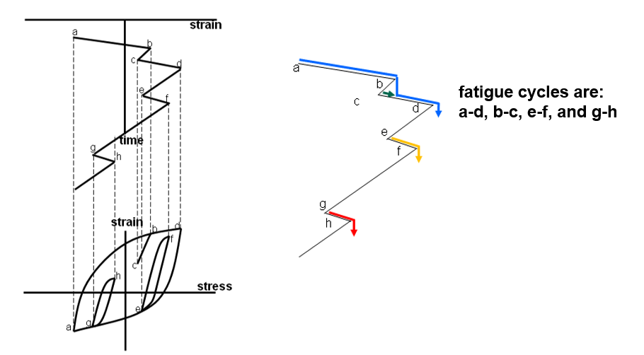
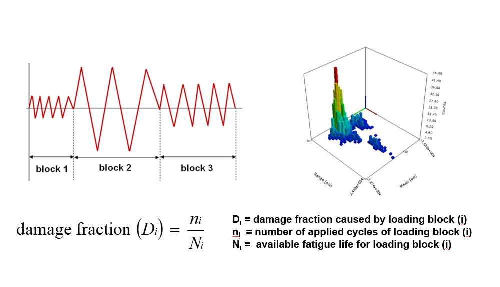
- Rainflow counting. Reduce variable-amplitude histories into cycles.
- Damage accumulation. Apply Palmgren-Miner to combine cycles across the spectrum. Keep an eye on overload/underload effects that can violate linear damage assumptions.
- Thermal cycles. For equipment with heat-up/cool-down, consider ε-N with thermo-mechanical coupling.
Weld Fatigue Design Model Setup: Avoid Common Traps
- Geometry fidelity where it matters
Resolve the weld toe radius or use a notch representation appropriate to your method. For structural stress, you don’t need the micro-radius; you need consistent extraction points.
- Mesh for fatigue, not just stress.
Ensure mesh independence at the extraction locations. Grow elements smoothly to avoid artificial peaks. For notch methods, keep aspect ratio and skewness in check.
- Loads and constraints that reflect reality
Replace rigid clamps with elastic supports when appropriate. Include preload, fit-up, and thermal fields if they exist in service.
- Residual stress treatment
If measured or expected, include as mean stress in your correction model or through a residual field in FEA. Post-weld heat treatment (PWHT) can reduce it; simulate both states if applicable.
What Actually Works
Geometric refinements
- Increase toe radius, add local thickness, or soften transitions.
- Relieve sharp attachments (doublers, brackets) with generous blends.
- Realign load paths to reduce secondary bending at the joint.
Process and material controls
- Specify weld quality class and finishing (toe grinding/TIG dressing/peening) to lower effective notch severity.
- Select filler/heat treatment for improved toughness and fatigue strength where feasible.
- Control heat input to limit distortion and residual tensile stresses.
Operational changes
- Reduce overload events or resonance through damping/isolation.
- Adjust start/stop sequences or pressure ramp rates to limit damaging cycles.
When Fracture Mechanics Becomes The Right Tool
Not every assessment starts at “no cracks.” If inspection finds an indication, or if a known discontinuity will persist, move to crack growth.
- Inputs: initial crack size (a₀), stress intensity range ΔK, threshold ΔK_th, and Paris law/C-m coefficients; for elastic-plastic, use J-integral approaches.
- Outputs: cycles to reach a critical size (ac), inspection intervals, and remaining useful life.
- ANSYS workflows: SMART Crack Growth can propagate a 3D crack under variable amplitude, while FEA post-processing provides SIFs/J for each step.
Pairing initiation life (ε-N) with propagation life (Paris law) gives a more complete lifecycle prediction for critical welds.
Verification: Correlate FEA With Strain Gauge Testing
A fatigue prediction gains credibility when the model reproduces the measured response.
- Instrument the hot spots with properly oriented rosettes.
- Recreate the duty cycle on the asset or test stand.
- Calibrate the model so that predicted surface strains match measured values at the same points (within agreed tolerances).
- Recompute life with the calibrated stress/strain fields.
- Set inspection and torque/fit-up procedures based on the verified analysis.
This loop transforms analysis into policy: defensible inspection intervals, torque charts, and training tied to the physics.
Weld Fatigue Design Checklist
- Select S-N vs ε-N based on expected plasticity and cycle regime.
- Match the stress definition to the chosen method (hot-spot, notch, or throat)
- Build a variable-amplitude spectrum with rainflow counting.
- Apply mean stress corrections consistent with the residual/operating mean.s
- Verify mesh independence at extraction points.
- Consider residual stress and thermal fields where relevant.
- Improve the joint via geometry, process, and operation, not one alone.
- Use fracture mechanics for known indications and inspection planning.
- Correlate predictions to strain gauge data before finalizing life and intervals
How SimuTech Group Can Help
- Weld fatigue design modeling: S-N, ε-N, mean stress, structural/hot-spot and notch approaches, weld detail categories
- Crack growth and fitness-for-service: SIF/J-integral, Paris law, variable-amplitude growth, inspection interval definition.
- Test correlation: On-site strain measurement, vibration/thermal logging, and model calibration to real loads
- Design improvement and policies: Geometry/process recommendations, torque and fit-up specs, inspection plans tied to predicted damage
Turn Repeat Failures Into Durable Fixes
If you need to turn a repeat weld issue into a durable fix with fewer prototypes and fewer returns, we’re ready to help. Connect with SimuTech Group to review your joint, your loading, and your targets, and we’ll build a fatigue strategy that holds up in the field and in the audit room.