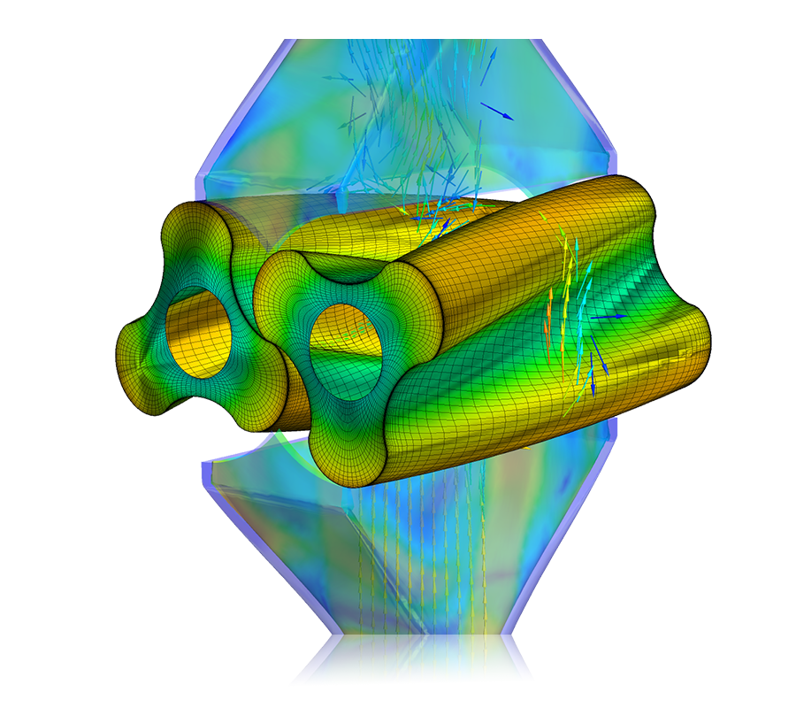
Ansys Mechanical Meshing | Webinar:
Learn the basic techniques for Ansys mechanical meshing when it comes to FEA. This includes 2D/3D Mesh Generation and Analysis for all finite element analysis-focused software types.

Ansys Mechanical Meshing | Background and Importance
For many businesses, simulation is an indispensable tool. The global market for simulation software is anticipated to expand at a compound annual growth rate (CAGR) of 17.1% from 2021 to 2028, according to Grand View Research. This is a significant growth, mostly because of the various advantages that simulation software offers to businesses, such as decreased expenses for product development, physical testing, and flawed prototypes.
Finite element analysis (FEA), computational fluid dynamics (CFD), and other types of software are available for product analysis in computer-aided engineering (CAE) applications like simulation. Pre-processing, solving, and post-processing are the three crucial processes in an analysis before running a CAE simulation. Let’s talk about the FEA pre-processing procedure and the significance of a high-quality mesh.
How to Get Ready for Meshing with CAD/Geometry in Ansys
It’s crucial to decide which CAD model characteristics from your FEA simulation application, such as Mechanical, need to be meshes and which don’t. For production purposes, CAD geometry is frequently quite intricate and detailed. However, for a simulation, you might not require every detail, in which case you might defeature, or remove, some of your geometry to save time.
For instance, your goods might be attached with a nameplate. The name plate may not require you to understand its physical consequences, thus it can be defeatured to avoid building a mesh, which reduces meshing and solving time.
The geometry of the link between two or more pieces is crucial when preparing your CAD model for simulation. It’s critical to choose whether your geometry will have a conformal or nonconformal mesh, for instance, if nodes are shared between similar faces (or edges). Parts that are glued or welded together are linked using a conformal mesh. When two pieces are connected by contacts or joints, a nonconformal mesh is utilized. You can combine these methods in Ansys Mechanical to suit your needs.
There are further methods that can give you more mesh control, but these default or automatic meshing techniques might be sufficient to get you where you need to go.
- For more on Ansys Mosaic Meshing Capabilities
- For more on Ansys Fluent Meshing Capabilities
- For more on Ansys Polyflow Meshing Capabilities
- For guidance on Ansys Post-Processing
- For Support on performing ‘EKILL‘ in Workbench
- APDL Command Objects post-Spectral Analysis
- For Separating DB Database Files from RST Files


