Mechanical Workbench | Multiple Step Analysis
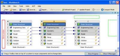
Have you ever wanted to rearrange the systems on the Project page? You can move linked and un-linked systems by selecting on Header Cell which is the one that says Static Structural, Modal, etc. After the Header Cell is selected, simply drag and drop to the new location. Consider the following linked analysis systems:
Project Page Schematics
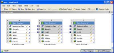
“Static Structural 2” can be moved in front of “Static Structural 1”. The Header Cell for “Static Structural 1” is selected with the left mouse button and can be dragged to any location highlighted with a dashed green box. When the cursor is placed over such a box, the “Move system” option is shown.
The resulting schematic is the following:
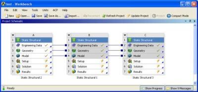
The first analysis system of a set of linked analysis systems cannot be deleted if it is in the first position. Rearranging the order allows deletion of the first analysis system. For example, “Static Structural 1” cannot be deleted until “Static Structural 2” or “Static Structural 3” is moved into the first position.
Multiple Step Analysis
A multiple step analysis can be defined in Workbench Mechanical using Analysis Settings. The Worksheet view of an example 4 step transient structural is shown below:
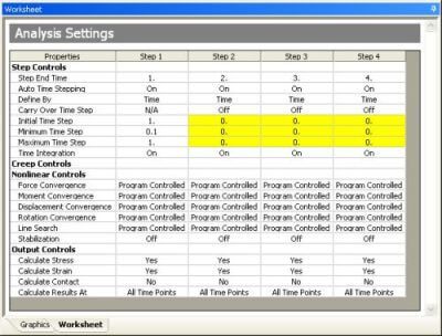
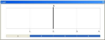
There are no default settings for the time steps. For a multiple step analysis, changing step controls on each individual step can be tedious. Multiple steps can be selected and changed simultaneously using the Graph window under Analysis Settings. Below, step 2 is selected by clicking on the bar under the graph. Note that “2” is highlighted in blue.
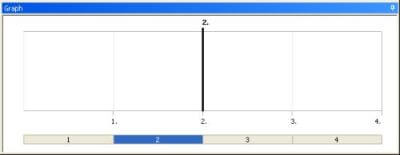
Multiple steps can be selected using typical “Shift” or “Ctrl” select. Steps 2, 3, and 4 are selected below.
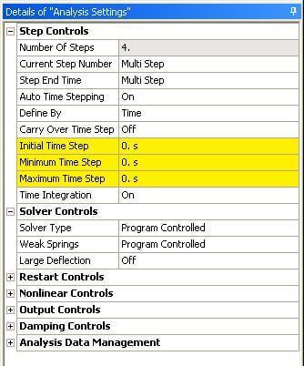
The Details of “Analysis Settings” is changed to Multi Step mode and the time steps can be changed simultaneously for steps 2, 3, and 4.
Need assistance with FEA modeling or optimizing your Ansys software? Click HERE for expert FEA engineering services!


