Induction Tube Heating Introduction
Heating fluid flows is often required in industry and laboratories but is not always easy to achieve. Some fluids can be heated with traditional combustion sources or through electric resistive methods. Using induction heating is challenging as most fluids are not conductive or magnetic. However, it is possible to heat the tubing that carries the fluids using induction heating, which introduces some advantages that can be very beneficial to many applications.
How is Induction Heating Used for Fluid Flow Heating?
The induction tube heating process is simple. Induction heating is used to heat a metallic tube, often stainless steel, that has an internal fluid flow, which is heated through convection.
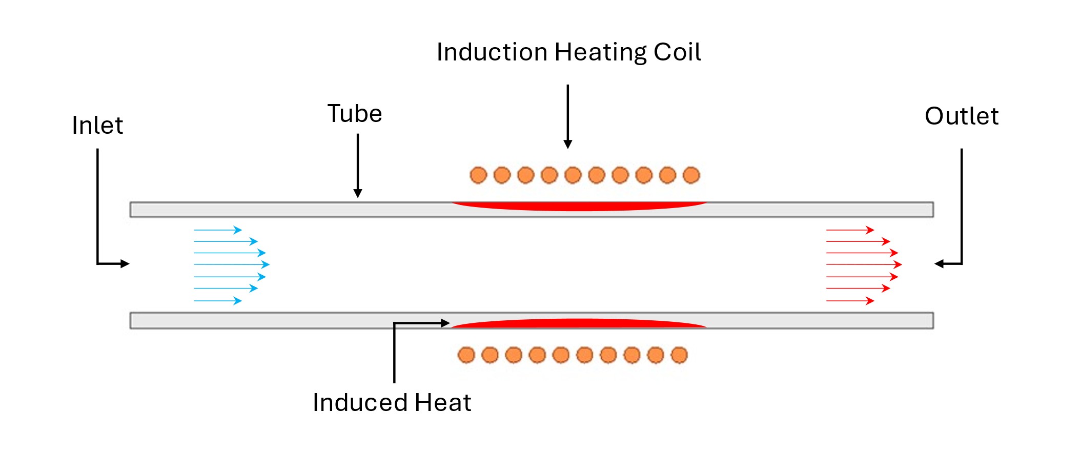
The image shows a schematic of the process. The cold fluid passes through the area heated by the coil, which is localized, and then exits it hotter due to convective heat transfer. While the image shows an open tube, it is possible to use this in closed systems as well.
Why Use Induction?
Induction heating has a few advantages:
- Clean: The process is clean and does not generate exhaust gas.
- Easy to Implement: There are times when the heating is needed in an existing system. If the coil can fit around the tube, induction has a high likelihood of being a good candidate with minimal modifications.
- Controllability: Since the power level can be easily adjusted and controlled from the power supply, the temperature can be controlled with temperature sensers and controllers.
- Rapid heating: The tube can be heated very rapidly, making the convective heat transfer the limiting process.
- Reliability: Properly designed and maintained coils can last a long time and experience very rare failures or downtime.
How is Induction Controlled?
As mentioned earlier the power level can be adjusted to achieve a desired temperature. There are different ways the system can be controlled:
- Manual control: This is the simplest form. Essentially, the power supply outputs a predefined excitation (voltage, current, or power). The predefined excitation can be a constant or variable. This requires the operator to manually adjust the excitation based on temperature or flow rates, if needed. This is an acceptable method for stable systems, labs, or if disturbances aren’t a concern.
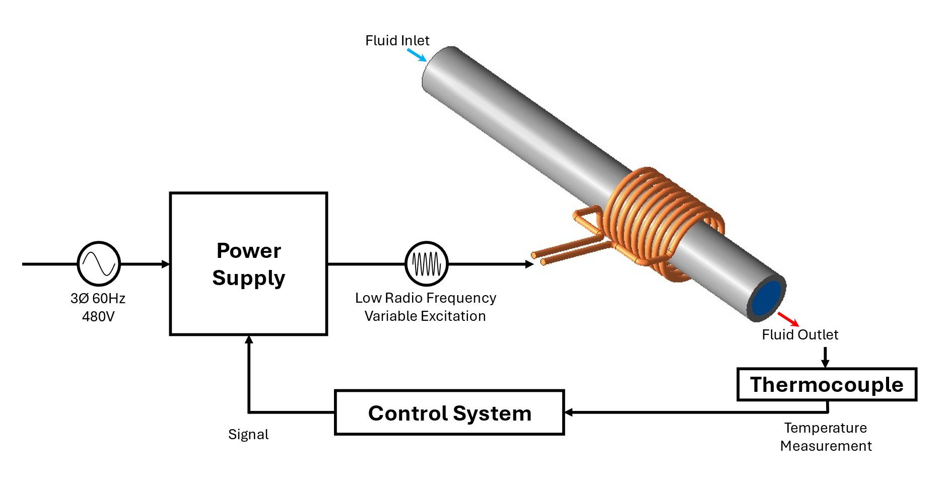
- Active control: In this method a control system, such as a PID, is used with temperature sensors, such as thermocouples, to adjust the excitation (voltage, current, or power) based on measured values.
Active control is very desirable as it adjusts for disturbances, logs results, and can be used for operation at different temperatures, making it highly applicable for laboratory and industrial settings. Furthermore, most modern induction heating power supplies have external control compatibility, making the process easy to implement for control engineers. The image below shows a simple schematic of how control is done.
Simulating Fluid Heating via Induction Heating
Induction tube heating simulation involves three physics of importance, making this a multiphysics application. First, the magnetic solution must be done to calculate the induced heat in the tube. Second, CFD (computational fluid dynamics) simulation is done to calculate the flow. Finally heat transfer is done between the fluid and the hot tube.
Using Ansys suite, we can use various tools to simulate the heating of fluid flow via tube heating.

Ansys Maxwell is used for the low frequency EM simulation. Maxwell is used to simulate the induced heating in the tube and coil and generate the volumetric heat load for the thermal solver. With input parameters like current and frequency, Maxwell is used to solve for inductance, voltage, power, and efficiency.
Since the CFD tools can simulate fluid flow and thermal solutions, one software is used for both. Ansys Icepak or Ansys Fluent can be used to simulate the fluid flow, tube heating, and heat transfer.
If needed, the resultant temperature can be returned to Maxwell to update the simulation for the new material properties. Temperature feedback can be used for steady state or transient simulations.
For simulations coupling Maxwell to Icepak, the entire simulation can be done in Ansys Electronic Desktop, while Maxwell-Fluent simulations can be done in Ansys Workbench or through manual mapping.
Example Simulation
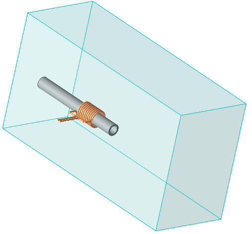
An induction tube heating simulation example was made using a stainless-steel tube heated by a 10 turn OD coil. Air was used as the heated fluid.
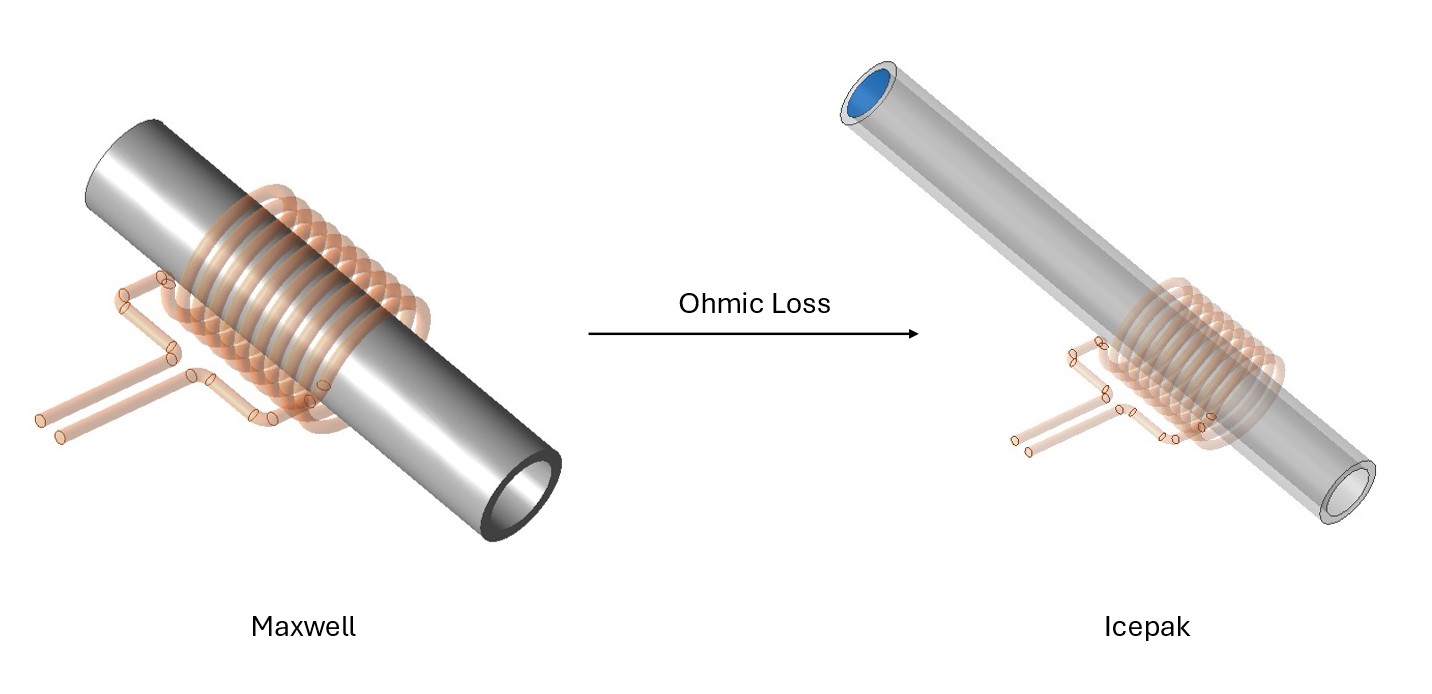
The magnetic simulation was solved in Maxwell and the induced losses were transferred to Icepak for the fluid and heat transfer simulation. The Maxwell simulation used a shorter tube to reduce the problem size and since the heating is local to the coil region.
The Icepak simulation has an air box to simulate the air exiting the tube shown in light blue in the image.
Finally, the coil current and inlet velocity were parameterized to investigate the effect of the current and inlet velocity on the temperature of the air exiting the tube.
Simulation Results
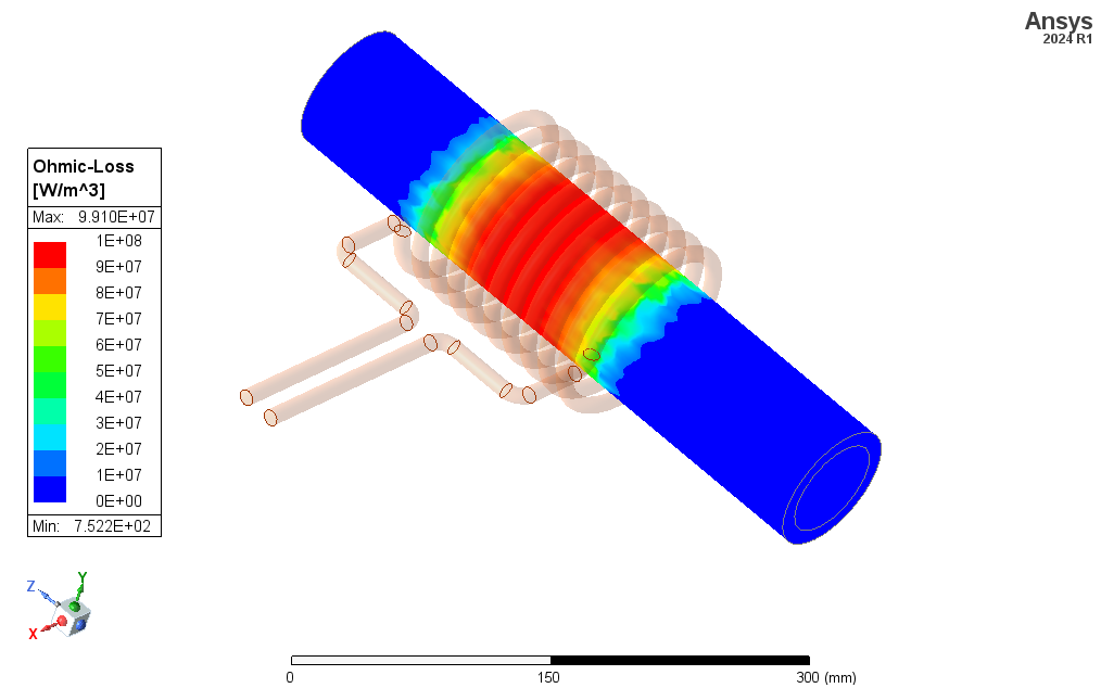
The image above shows the induced loss in the tube from the Maxwell simulation.
The temperature of the air exiting the tube for the base simulation of 900 A coil current and 15 m/s at different distances from the outlet is shown in the image above.
The image above shows the air’s temperature at the tube’s exit at different orientations.

The image above shows the air’s temperature at different coil currents at the baseline inlet velocity of 15 m/s. The image below shows the air’s temperature at different inlet velocities at the baseline inlet current of 900 A.
Accelerate Fluid Heating with Induction Tube Simulation
At SimuTech Group, we help engineers design and optimize induction-heated tube systems to reach target outlet temperatures quickly and reliably. From coil geometry and frequency/power selection to material choices, our team couples Ansys Maxwell with Fluent/Icepak to model electromagnetic losses, conjugate heat transfer, and flow behavior.
Contact us today to see how induction tube heating simulation can shorten lab iterations, de-risk scale-up, and improve efficiency in your fluid-heating applications.

Tareq Eddir, B.S.E. Chemical Engineering
Senior Staff Engineer, SimuTech Group
Tareq has worked in the induction heating industry for over eight years with experience in simulating, optimizing, consulting, testing and troubleshooting induction heating applications. His work includes leading a host of interesting projects across various industries, including heat treatment, melting, shrink fitting, and much more. He has been a member of SimuTech Group’s low frequency electrical team since 2022, with interest in low frequency and thermal coupled simulations.