Contact Us
Explore how porous media models can efficiently represent complex components in polymer processing applications, followed by a practical Fluent Polyflow demonstration.
Introduction to Ansys Fluent Polyflow Porous Media
Simulation has become an essential engineering tool for evaluating product performance, optimizing manufacturing processes, and reducing development time and costs. By predicting flow behavior under realistic operating conditions, engineers can make better design decisions while minimizing the need for costly physical prototypes.
Many industrial systems include components with complex internal structures that are impractical to model in full detail. Instead, these components can often be represented as porous media, enabling accurate prediction of pressure losses and flow distribution while significantly reducing computational cost. This approach has become a practical solution for a wide range of engineering applications.
Challenges in Porous Media
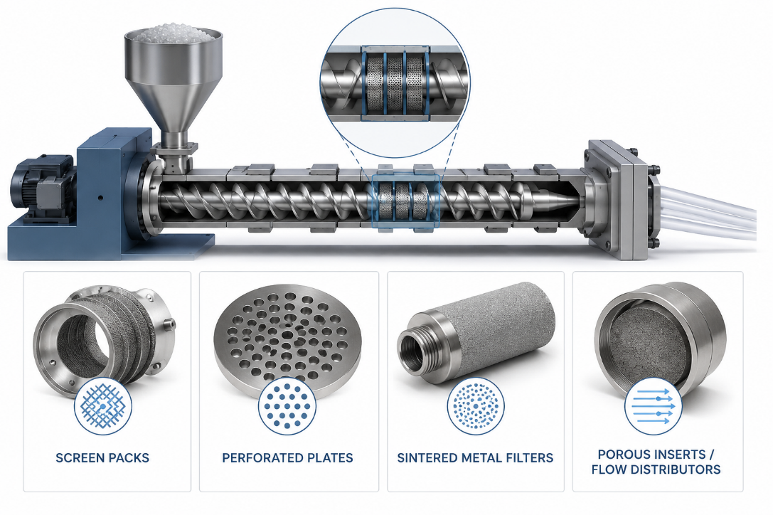
Many polymer processing systems incorporate components that significantly influence flow behavior but are difficult to model explicitly due to their complex internal geometry. Common examples include fiber preforms in resin transfer molding (RTM), screen packs and perforated breaker plates in extrusion lines, sintered metal filters, and porous inserts used to distribute or condition the polymer melt. These components play a critical role in pressure drop, flow uniformity, filtration efficiency, and overall process performance.
Representing every fiber, wire, hole, or pore within these components can result in extremely large meshes, long simulation times, and high memory requirements. Instead, many of these structures can be represented by an equivalent porous media model that reproduces their hydraulic behavior without resolving the microscopic details. This approach enables engineers to evaluate realistic industrial systems more efficiently while maintaining the level of accuracy required for engineering design and process optimization.
Engineering Solutions
Methods
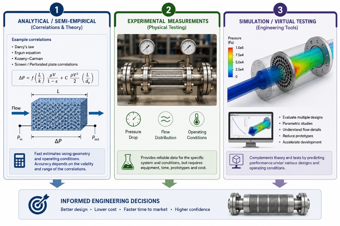
The hydraulic performance of components such as screen packs, perforated breaker plates, fiber preforms, and porous inserts is commonly evaluated using analytical and semi-empirical correlations, experimental measurements, or a combination of both. These methods relate parameters such as pressure drop, permeability, and flow resistance to the geometry and operating conditions of the component, providing practical engineering tools for design and validation.
Although these approaches are widely accepted, they are not always applicable to complex industrial systems. Suitable correlations may not exist for customized geometries or specific process conditions, while experimental testing often requires multiple prototypes, specialized equipment, and considerable time and cost. As a result, engineers increasingly rely on simulation to complement traditional methods, enabling virtual evaluation of different design alternatives before physical validation.
Solutions
Simulation has become a valuable complement to analytical methods and experimental testing, enabling engineers to evaluate design alternatives earlier in the development process while reducing the need for multiple physical prototypes. By accurately predicting flow behavior and pressure losses, simulation helps shorten design cycles, optimize component performance, and lower development costs.
Ansys Fluent Polyflow provides an efficient framework for modeling flow through porous media commonly encountered in polymer processing applications. Instead of explicitly resolving complex internal structures such as screen packs, perforated breaker plates, fiber preforms, or porous inserts, these components can be represented using equivalent porous media properties, including permeability and void fraction. This approach preserves the overall hydraulic behavior of the component while significantly reducing computational effort.
Fluent Polyflow incorporates the Darcy model to simulate flow through porous media, where the flow behavior is defined by the relationship between the pressure gradient and fluid velocity. This formulation is well suited for applications such as polymer melt filtration, resin transfer molding, and other polymer processing operations involving slow flow through porous structures.
The following example demonstrates the complete workflow for setting up a porous media model in Fluent Polyflow, from geometry creation and meshing to model configuration, solution, and post-processing of the results.
Ansys Fluent Polyflow Porous Media Simulation Workflow
Geometry and Mesh
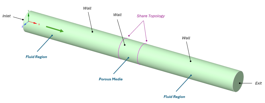
The model consists of three coaxial cylinders with an inner diameter of 20 mm. These represent two polymer melt flow domains separated by a porous medium modeled using the Darcy formulation. The dimensions of each region and the applied boundary conditions are illustrated in the figure below.
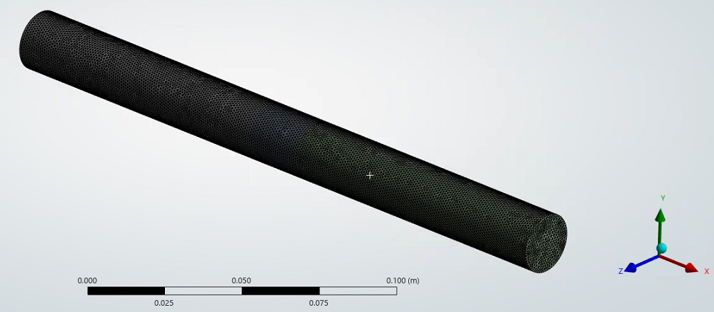
The computational mesh was generated using Ansys Meshing. For this demonstration, the model contains approximately 597k tetrahedral elements. The mesh quality metrics were verified and found to be within the recommended guidelines, ensuring a reliable numerical solution.

Model Setup
The mesh generated in Ansys Meshing is first imported into Ansys Fluent Polyflow. Although the recommended format is .poly, .msh files are also supported for our porous media example. The mesh can be loaded from File > Read > Mesh.
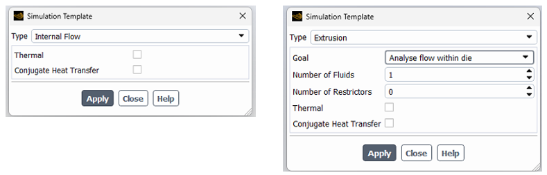
To simplify the model setup, Fluent Polyflow provides several predefined templates that automatically configure the appropriate physics and solver settings for common polymer processing applications. These templates help streamline the workflow and reduce the amount of manual configuration required. For this demonstration, either of the following templates can be used, as both produce equivalent results for this model (it also works without templates):
- Inlet: Mass flow rate of 0.0015 kg/s.
- Outlet: Zero gauge pressure.
- Walls: No slip. For the porous media, no specifications are required for the external wall.
- Porous media: Void of 0.8 and permeability of 1e-16 m2.
- Interfaces: Fluid-Porous.
- Material: HPDE for extrusion.
Solution
The simulation was completed in 9 minutes using 10 CPU cores on a workstation equipped with a 12th Generation Intel® processor. The maximum memory consumption during the analysis was approximately 6 GB of RAM, demonstrating the computational efficiency of the porous media approach.
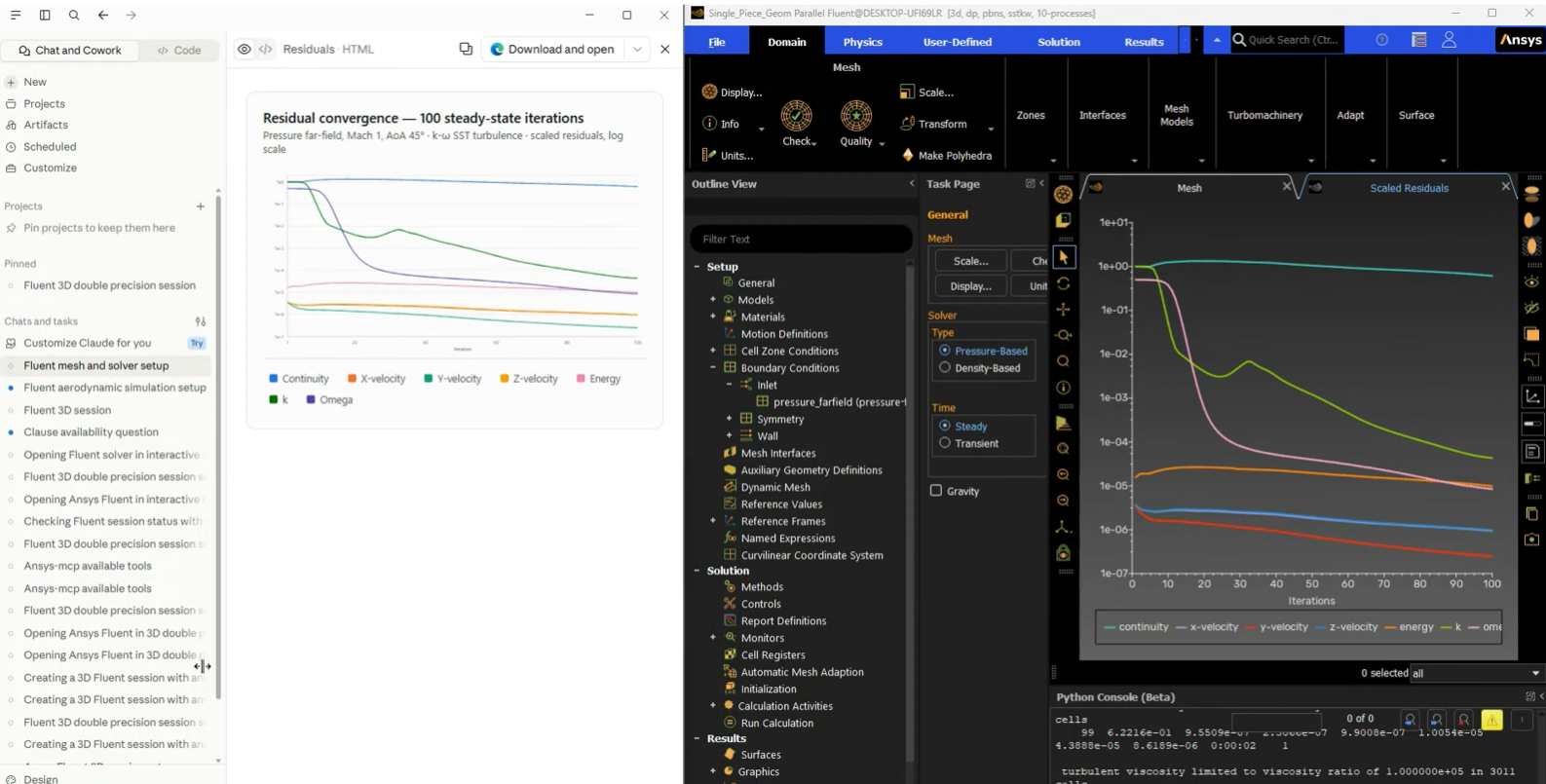
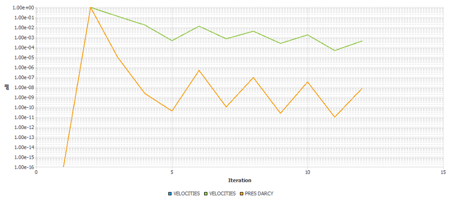
The convergence history is presented below, showing the residual evolution for the velocity and pressure variables associated with the Darcy porous media model. The residuals decrease smoothly and reach the prescribed convergence criteria, indicating a stable and well-converged numerical solution.
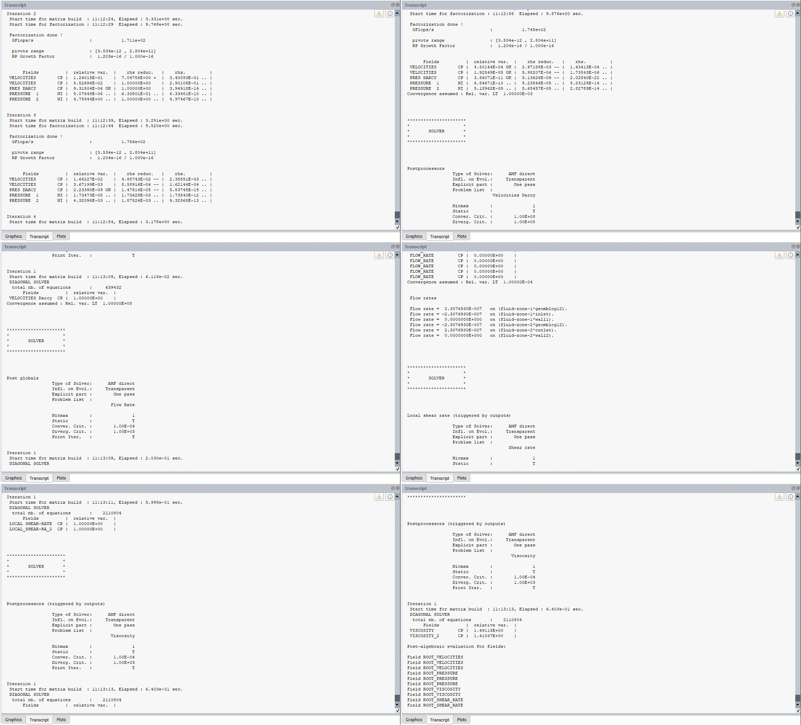
The following is a short sequence of the convergence process:
Results
The contour plots below illustrate the flow behavior as the polymer melt passes through the porous media. Ansys Fluent Polyflow creates contour plots for each domain, but the results are combined in the variables with the prefix ROOT.
ROOT_PRESSURE
A nearly linear pressure distribution is observed within the inlet and outlet fluid regions, while the largest pressure gradient occurs across the porous medium. This behavior is expected, as the porous region introduces additional hydraulic resistance that produces most of the pressure drop. The results demonstrate that the Darcy model successfully captures the resistance imposed by the porous component without explicitly resolving its internal structure.
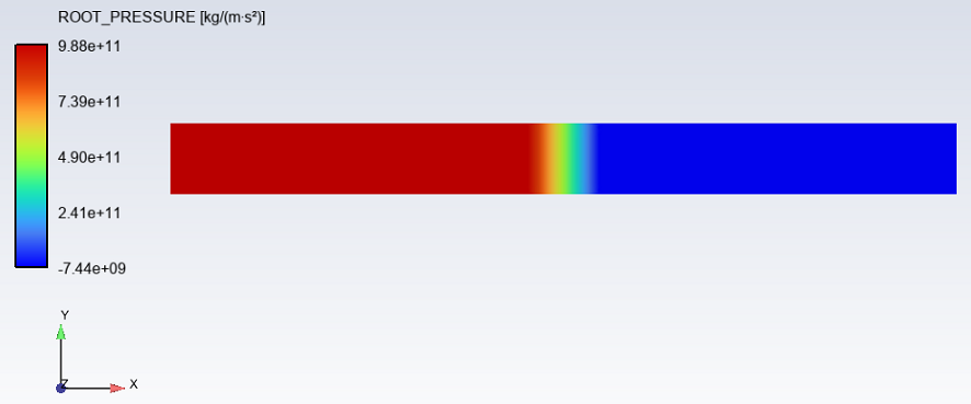
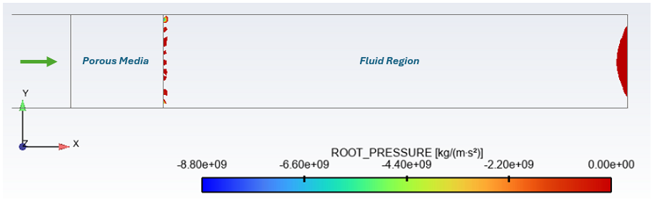
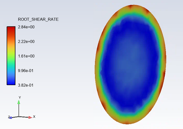
Notice that the minimum value of the pressure is negative while the gauge pressure was set up as zero in the setup. Polyflow uses the Finite Element Method to perform the calculations, and for an incompressible flow the velocity field is the primary unknown, the incompressibility condition is the constraint, and the pressure field is the mathematical Lagrange multiplier in the Navier-Stokes equations associated with that constraint. The following pictures show the regions where the negative pressure is located and the pressure at the outlet region (local values for both).
ROOT_VELOCITIES
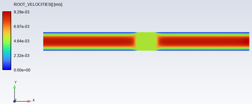
The velocity profile remains fully developed in the inlet and outlet sections due to the constant pipe diameter. Within the porous region, the velocity distribution becomes more uniform as the flow is governed by the porous media formulation rather than the classical no-slip wall behavior. Since the cross-sectional area remains unchanged, the average flow rate is conserved throughout the domain.
ROOT_SHEAR_RATE
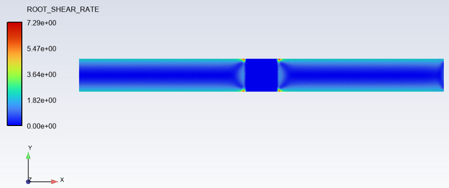
The shear rate is highest near the pipe walls in the fluid regions, where velocity gradients are largest. Inside the porous medium, the shear rate decreases significantly because the flow is represented as a continuum through the Darcy model instead of explicitly resolving the microscopic velocity gradients around pores or fibers. Small localized variations are observed at the fluid–porous interfaces, reflecting the transition between the free-flow and porous domains.
Need help modeling porous media in Ansys Fluent Polyflow?
SimuTech Group’s Fluids engineers can help your team model porous media in Ansys Fluent Polyflow, evaluate pressure drop and flow distribution, and develop efficient simulation workflows for extrusion, filtration, resin transfer molding, and other polymer-processing applications. Connect with SimuTech Group to discuss your project.

Germán Ibarra, MSc Energy Engineering
Senior Staff Engineer – Fluids, SimuTech Group
Germán Ibarra is a mechanical engineer with a master’s degree in Energy Engineering and more than 14 years of experience in research, development, and engineering analysis. At SimuTech Group, he supports simulation-driven workflows for complex engineering applications, including polymer processing, thermal-fluid behavior, and manufacturing process optimization. His background spans R&D, project development, and technical education, helping engineering teams apply numerical simulation to better understand product performance, reduce physical testing, and improve design decisions.