Contact Us
Overview
As wireless communication systems continue to evolve, engineers are constantly seeking innovative ways to improve antenna performance while minimizing unwanted electromagnetic effects. One of the most effective solutions is the use of Electromagnetic Band Gap (EBG) structures—engineered periodic surfaces that suppress surface waves, reduce mutual coupling, and enhance radiation efficiency.
In this blog, we illustrate how EBG structures can be accurately designed and optimized using Ansys HFSS simulation workflows.
Electromagnetic Band Gap (EBG) Structures
An Electromagnetic Band Gap structure is a periodic arrangement of conductive or dielectric elements that prevents electromagnetic waves from propagating within specific frequency ranges. Unlike conventional materials, EBG structures are engineered to manipulate electromagnetic waves, making them valuable in applications such as:
- Phased array antennas
- High-gain antenna systems
- Radar platforms
- Satellite communications
- 5G and 6G wireless systems
- Microwave circuits
- Electromagnetic interference (EMI) suppression
EBG Simulation Approaches
By carefully selecting the geometry and periodic spacing of the unit cell, engineers can tailor the band gap to meet specific design requirements. Modeling an entire periodic surface can require enormous computational resources. Fortunately, Ansys HFSS EBG simulation allows engineers to use electromagnetic periodicity to simulate only a single unit cell while accurately predicting the behavior of an infinitely repeating structure. There are two common approaches to analyzing EBG unit cells with HFSS:
Reflection Phase Method
In this method, a Floquet port is used to excite the unit cell with a plane wave and measure the reflection from the unit cell. To emulate an infinite periodic surface, lattice pair boundary conditions are applied to the sides of the unit cell airbox.
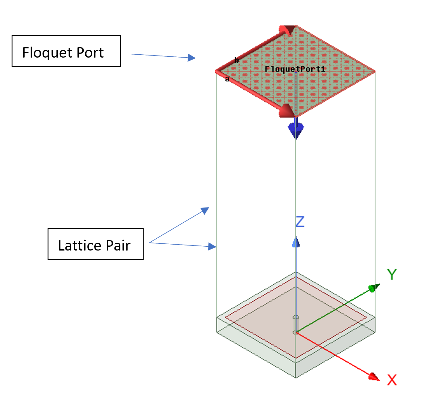
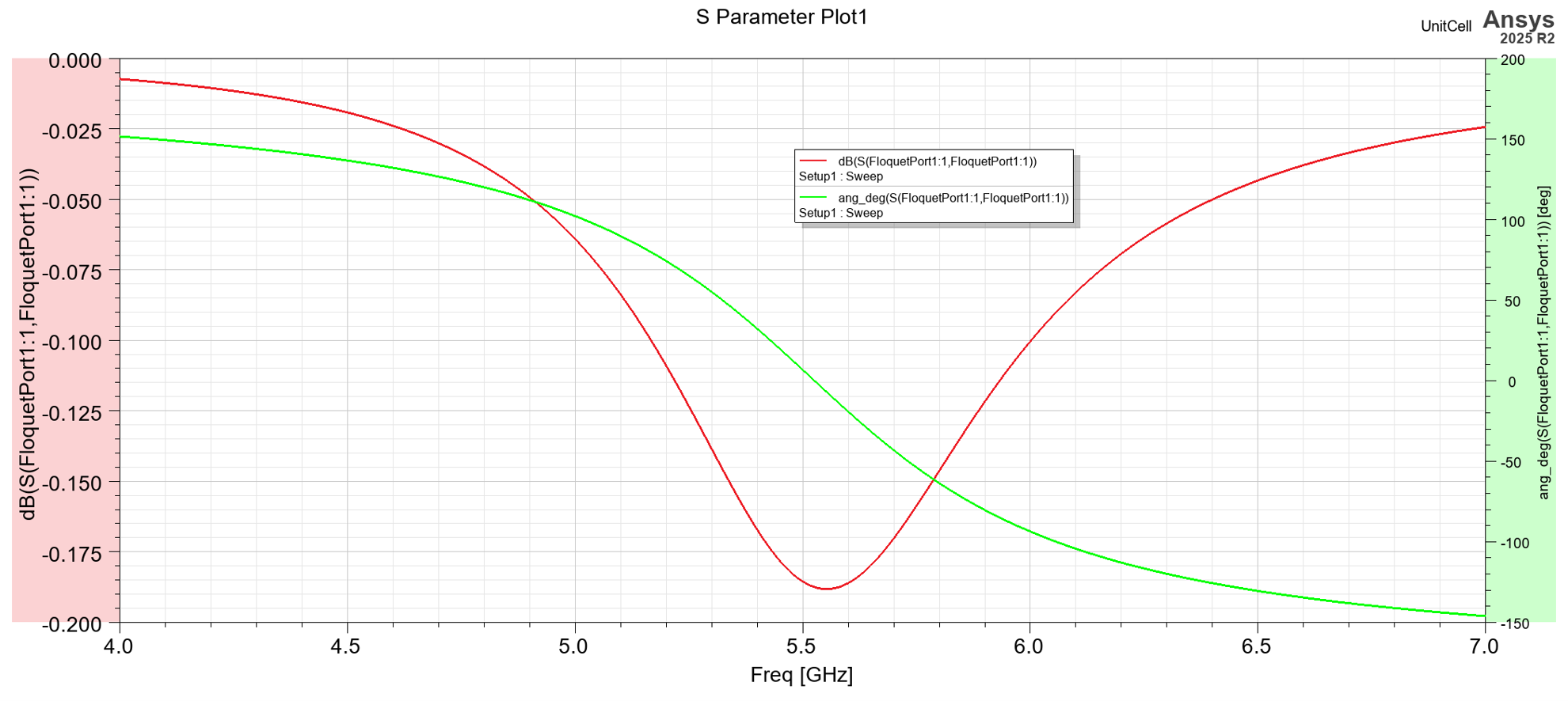
Below is an example of a simulated EBG unit cell model. As we can see, the unit cell shows a resonance at 5.5 GHz.
Dispersion Method
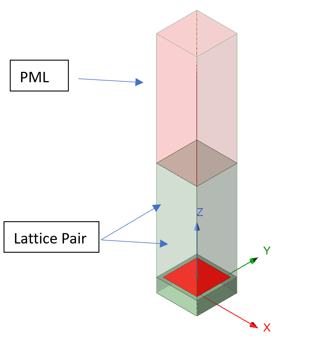
In the dispersion method, the Eigen-mode solver is used to find the frequency of natural resonance for the EBG unit cell. In Ansys HFSS EBG simulation, lattice pair boundary conditions are applied to the sides of the unit cell to emulate an infinite periodic surface. These boundaries introduce phase shifts between adjacent cells, allowing engineers to investigate how electromagnetic waves propagate through the structure at different scan angles and propagation directions. By parametrizing the phase delay between the lattice pair boundaries, engineers can sweep the projected wave vector and find the resonant frequencies as a function of the projected wave vector. This approach is equivalent to varying the angle of incidence, allowing the dispersion diagram to be created.
Understanding Dispersion Diagrams
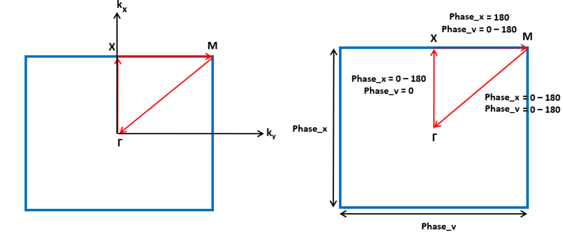
Ansys HFSS EBG simulation uses dispersion diagrams to relate frequency to the propagation constant, or wave vector, providing insight into how electromagnetic waves travel through the periodic structure. For a periodic EBG structure, the dispersion curve is periodic along the k axis, therefore, we need to plot the dispersion curve only within one single period. This period is known as the Brillouin zone. We can define all the propagating vectors in the Brillouin zone and obtain the entire periodic structure characteristics. For a square shape EBG, the Brillouin zone is a triangle as shown in the figure below, therefore 3 sweeps need to be solved for solution modes along the Γ-X-M triangle following the standard path:
- Γ – X
- X – M
- M – Γ
Reviewing Ansys HFSS EBG Simulation Dispersion Results
Within this frequency range:
- Surface waves are suppressed.
- Mutual coupling between antennas is reduced.
- Unwanted resonances are minimized.
- Radiation efficiency improves.
- Antenna isolation increases.
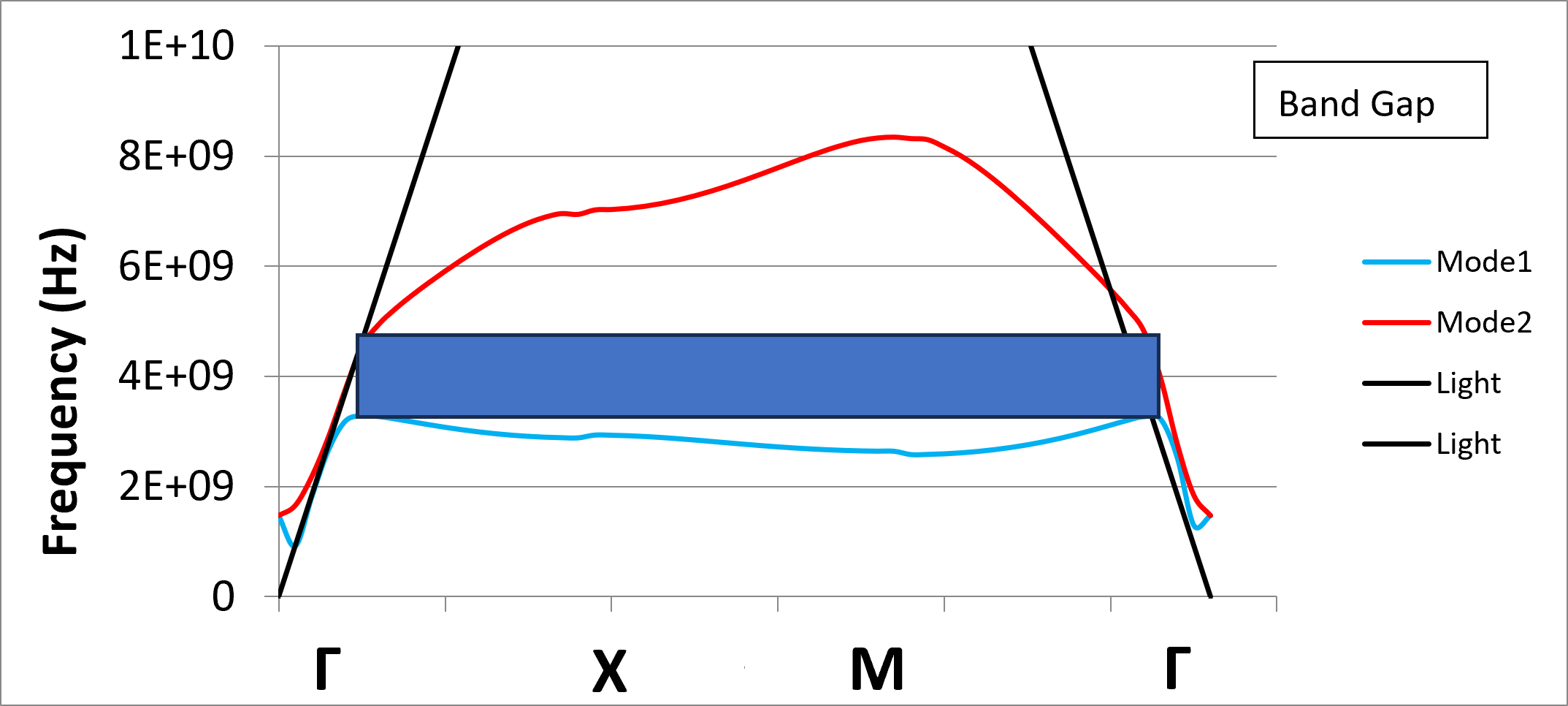
This information allows engineers to fine-tune the unit cell dimensions until the desired operating frequency lies within the electromagnetic band gap.
Ansys HFSS EBG Simulation: In Conclusion
EBG structures have become a key technology in modern antenna and RF design, offering effective solutions for surface-wave suppression, mutual coupling reduction, and enhanced electromagnetic performance.
By combining periodic boundary conditions with dispersion analysis, engineers can accurately predict the behavior of complex periodic structures using only a single unit cell. This Ansys HFSS simulation-driven EBG workflow accelerates development, reduces design risk, and enables the creation of high-performance antennas and microwave devices for next-generation aerospace, defense, wireless, and satellite communication systems.
Continue Learning in the SimuTech Skills Center
Want to see the full workflow in action? Watch the related SkillsCenter recordings in the SimuTech Customer Center to learn more about EBG analysis with Ansys HFSS.

Ibrahim Nassar, PhD
Lead Engineer – RF/Microwave, SimuTech Group
Ibrahim Nassar, PhD, is a Lead Engineer – RF/Microwave at SimuTech Group. He has 15+ years of experience in RF/Microwave and antenna design, complemented by a strong background in Power and Signal Integrity (PI/SI) analysis. He specializes in antenna, RF, microwave, and electromagnetic design, with experience in antennas and propagation, wireless sensing, harmonic radar, compact antenna design, and high-frequency electromagnetic simulation.