Contact Us
Introduction to Phased Array Reflector Simulation
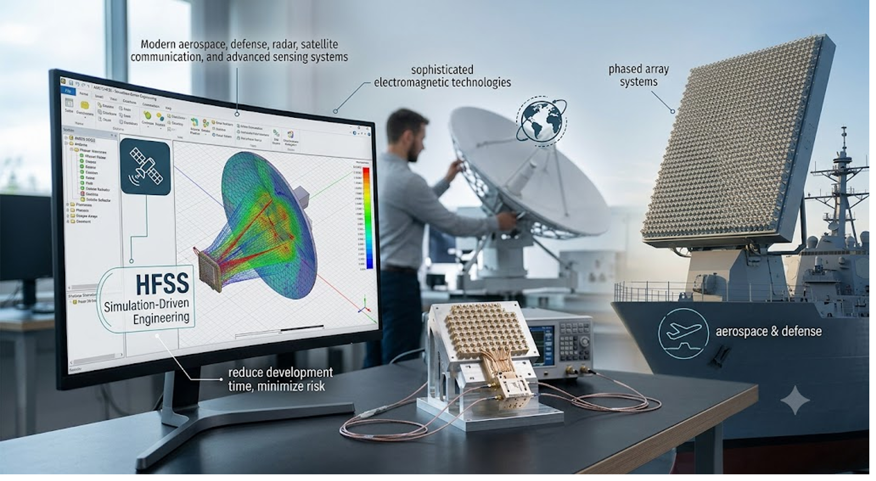
Ansys HFSS phased array reflector simulation helps engineers model, analyze, and optimize complex antenna systems before physical prototyping. In aerospace, defense, radar, satellite communications, and advanced sensing applications, phased array systems must meet demanding requirements for beam steering, gain, signal control, and overall electromagnetic performance.
This blog highlights a phased array fed reflector workflow using Ansys HFSS. The demonstration shows how engineers can use 3D component arrays, FEM regions, and SBR+ techniques to model large antenna structures more efficiently while maintaining accuracy for key performance behaviors.
Simulating Phased Array Fed Reflector Systems in Ansys HFSS
Phased array reflector systems are widely used in applications where precision beam steering, high gain performance, and adaptive signal control are critical. These systems are commonly found in:
- Aerospace and defense radar platforms
- Satellite communications
- Advanced wireless infrastructure
- Electronic warfare systems
- Remote sensing and surveillance technologies
- Autonomous systems and navigation platforms
Designing these systems presents several engineering challenges. Teams must account for electromagnetic coupling, antenna performance, reflector geometry, beam characteristics, material properties, and overall system efficiency — all while balancing size, weight, cost, and manufacturability.
3D Component Array Method (CADDM)
The 3D component array technique is the most efficient way to simulate large and complex arrays. It uses an efficient domain-decomposition-based finite element technique to model finite semi-periodic structures with non-identical unit cells, thereby increasing flexibility. Compared to FADDM, unit cells in this method must be defined as 3D components. This simulation technique enables faster simulation and less memory usage compared to FADDM, distributed computing resources. The overall workflow begins by importing the 3D components into HFSS, which represent different unit cells in the model. Then the array is created similarly to creating a finite array from a unit cell. However, this method lists all unit cell components and allows any arrangement of those unit cells within the array dimensions defined by the user.
3D Component Array Requirements
To use the 3D Component Finite Array workflow with non-identical unit cells, the unit cells must meet the following requirements:
- Unit cells must be defined as 3D Components
- Dimensions of unit cells’ bounding boxes must be identical
- Appropriate Lattice Pairs and boundary conditions must be defined on the surfaces of unit cells
Demonstrating a Phased Array Reflector Workflow
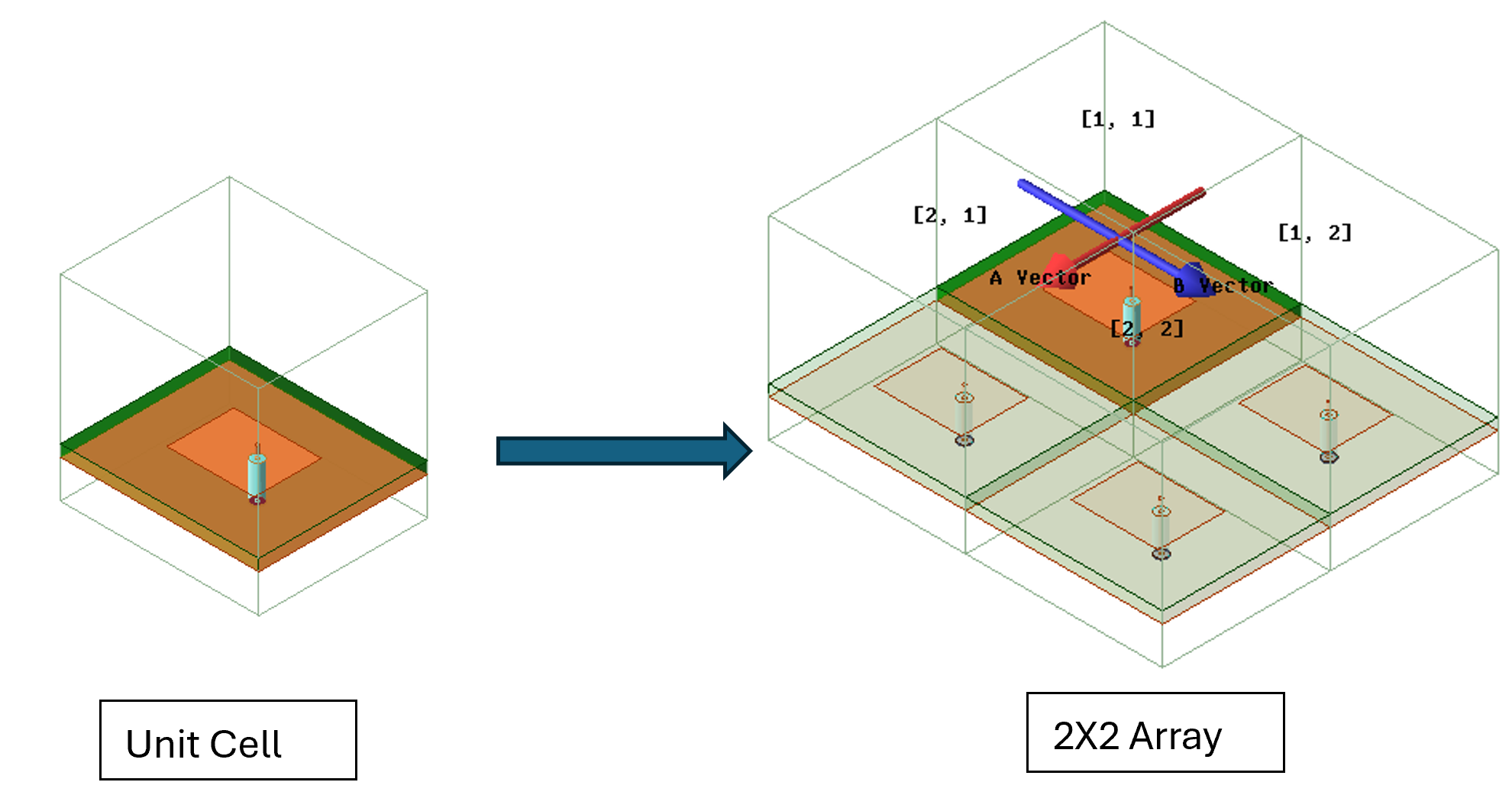
In this demonstration, Ansys HFSS is used to create and analyze a phased array reflector configuration. The workflow begins with the construction of the phased array structure. Below is an example of a simple 2X2 patch array modeled and simulated using the 3D component array technique. The process starts by creating a 3D component unit cell modeled with periodic boundary conditions. Once the 3D component is inserted, the Create Array command is enabled to build the array and designate the active unit cells.
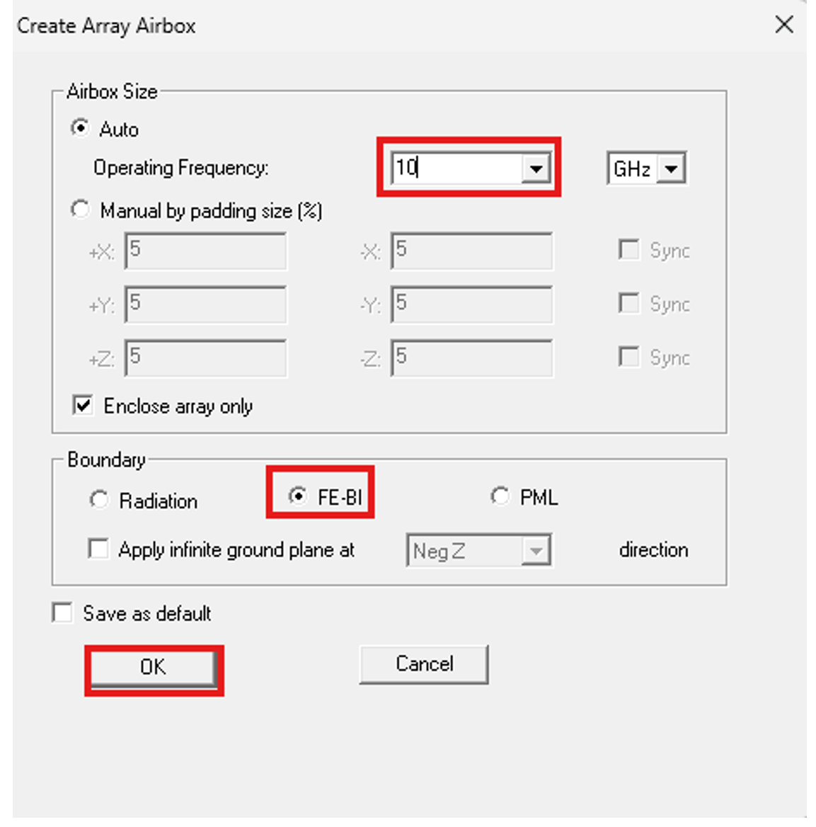
After the array is created, the Create Array Airbox Enclosure option is enabled. This option allows to add arbitrary native FEM geometries around the component array, as long as all geometries are enclosed by an airbox. The boundary assignment of interest for the air box in this is example is the FE-BI option, as it supports Shooting and Bouncing Rays (SBR+) regions.
Optimizing Reflector Geometry and Focal Point Performance
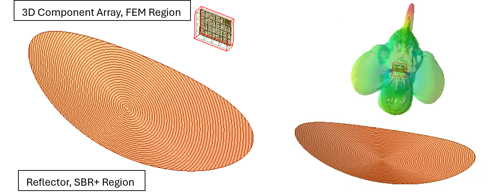
As our Ansys HFSS phased array workflow progresses, the reflector surface is developed and refined to support the desired electromagnetic behavior. Engineers can evaluate how reflector geometry influences beam performance, focal characteristics, and signal distribution across the array. Using hybrid regions by combining the 3D component array FEM region with SBR+, we can take advantage of leveraging the current component array and SBR+ techniques and workflows. This can provide significant enhancement to the design and simulation efficiency for solving electrically large problems. It gives the full wave accuracy for the phase array model and asymptotic speed where the reflector is large in terms of wavelength.
Optimizing Reflector Geometry and Focal Point Performance
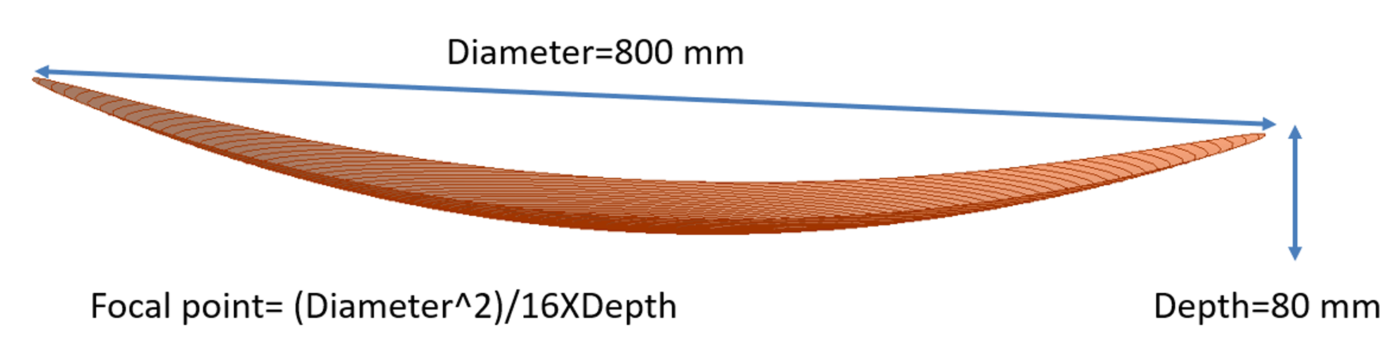
The workflow can also include parameterization and automation to simplify complex design studies. HFSS can evaluate numerous configurations digitally, dramatically reducing development time. Figure 5 below shows the equation that can be used to approximate the focal point. The focal point can be parametrized and then optimized for higher gain with significant reduction in simulation time by re using the converged mesh while maintaining high levels of accuracy.
Watch the Full Ansys HFSS Phased Array Reflector Simulation Demo
This video demonstration walks through the phased array fed reflector workflow in Ansys HFSS, including 3D component array setup, airbox enclosure creation, FEM and SBR+ region usage, and reflector performance evaluation.
Working on a complex antenna design?
Connect with SimuTech Group to explore how Ansys HFSS simulation workflows can support phased array, reflector, radar, and high-frequency electromagnetic applications.

Ibrahim Nassar, PhD
Lead Engineer – RF/Microwave, SimuTech Group
Ibrahim Nassar, PhD, is a Lead Engineer – RF/Microwave at SimuTech Group. He has 15+ years of experience in RF/Microwave and antenna design, complemented by a strong background in Power and Signal Integrity (PI/SI) analysis. He specializes in antenna, RF, microwave, and electromagnetic design, with experience in antennas and propagation, wireless sensing, harmonic radar, compact antenna design, and high-frequency electromagnetic simulation.