How a Beam Expander Works
Beam expanders are used to increase the diameter of a collimated beam of light, such as a laser beam, while preserving its collimation. It is commonly used in laser optics and other applications where modifying the beam’s size or divergence is necessary.
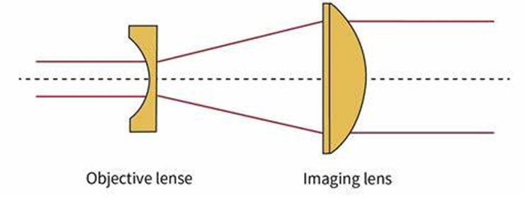
In a typical beam expander, the input beam is a collimated laser or light beam that enters the first optical element. When the beam is expanding, the first optical element changes the incoming beam’s divergence, and the second optical element re-collimates it, resulting in a larger diameter. The beam expansion ratio M is determined by the focal lengths of the two lenses or mirrors:
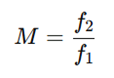
Where f1 and f2 are the focal lengths of the first and second optical elements.
Setting Up a Beam Expander Model in Zemax Sequential Mode
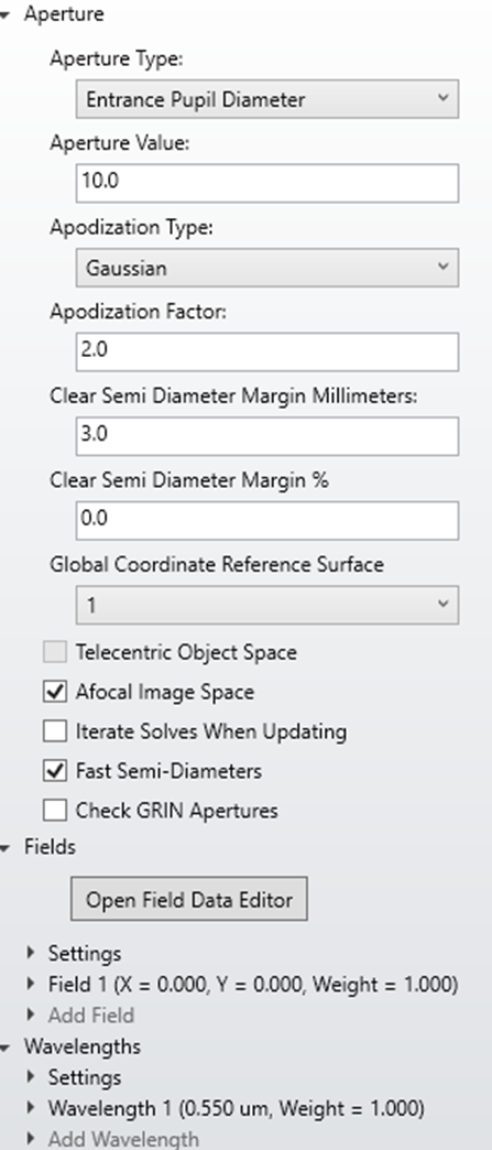
When creating a beam expander model in Ansys Zemax OpticStudio, typically in sequential mode, it involves setting up lenses or mirrors to expand a collimated beam of light. The sequential mode is ideal for designing lens-based beam expanders. Below is an example. By defining the system wavelength (550 nm) and entrance pupil diameter (10 mm) in the system explorer, the two lenses are to be defined. The beam is defined as a Gaussian Apodization, with a factor of 2. Since the output of the beam expander is a collimated beam, the “Afocal Image Space” should be selected.
Lens Data and Merit Function Setup
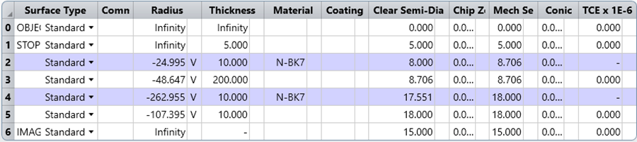
The lens data of the beam expander are listed below. Two N-BK7 lenses are used, with all four radii of each single lens set as variables. The distance between the two lenses, set to 200 mm here, is geometrically related to the beam’s expansion at the input.
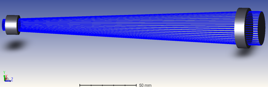
The resulting beam expander structure is shown below, with 45 rays arranged in a ring.
Some merit function operands are applied here to limit and optimize this beam expander structure.
- REAY reads the local real ray y-coordinate in lens units at surface No. 6, the image plane. This operand directly defines the output beam width as 15 mm — 3× the input beam radius of 5 mm.
- MNCA and MXCA constrain the distance (i.e., the air center thickness of the overall lens from surface 1 to 5) to a range of 0.5 mm to 1 m.
- MNEA sets the minimum edge thickness of air between the second lens and the image plane to 0.5 mm.
- MNCG and MXCG limit the center thickness of both lenses to between 2 mm and 15 mm.
- MNEG limits the edge thickness of both components to a minimum of 2 mm.
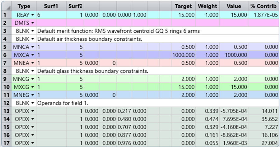
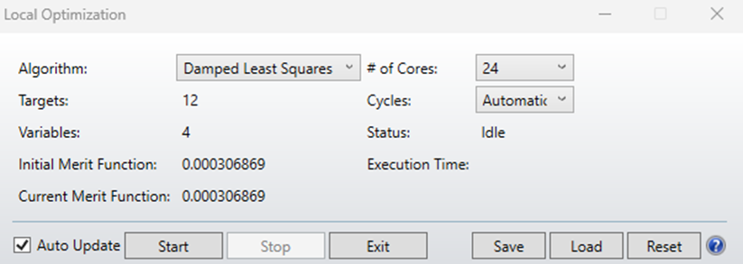
These constraints produce a merit function value of 0.0003 after optimization. The limits and requirements are reasonable and achievable.
Prescription Data and Interference Analysis
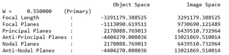
After optimization, both focal lengths in object and image spaces approach infinity, indicating a successful optimization of an afocal system.
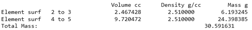
For manufacturing purposes, the volumes and masses of both lens elements are estimated using the format below. The density value is in g/cc and was exported from the materials library.
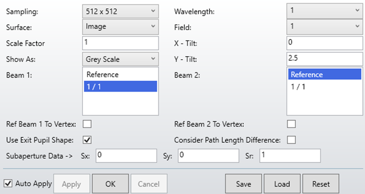
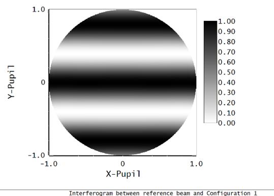
Since the input is coherent light (i.e., a single wavelength), the image plane will exhibit interference when the angle of incidence is tilted. The interferogram below shows the exit pupil shape at a y-tilt of 2.5 degrees, demonstrating that the beam expander induces interference from a tilted input beam.
Looking to design and optimize beam expanders or other optical systems? SimuTech Group’s Zemax 101 training course covers the fundamentals of optical design in OpticStudio, including optimization techniques and merit function setup. For more on what Zemax offers across your full design workflow, read our guide to maximizing optical workflows with Ansys Zemax. Contact us to discuss your optical design needs.