Discover how to create efficient blade models with our detailed step-by-step workflow, guiding you smoothly from initial geometry to advanced simulations.
Why Blade Modeling Requires a Structured Simulation Workflow
The process of blade modeling presents several challenges. One of the primary difficulties is accurately capturing the intricate geometry. Blade designs often feature complex curves and fine details that need precise modeling to ensure performance and reliability.
Another significant challenge is transitioning from geometry to a mesh that is suitable for simulation. The meshing process requires careful consideration to balance detail and computational efficiency. Inadequate meshing can lead to inaccurate simulation results, while overly detailed meshes can cause prohibitive computational costs.
Finally, simulating the blade’s performance under various operating conditions is crucial. This stage must account for factors such as aerodynamic forces, material stresses, and thermal effects, each of which requires specialized simulation approaches and tools.
Ansys Tools for the Complete Blade Modeling Workflow
To address these challenges, a structured workflow is essential. Ansys provides all the necessary tools for each step of the workflow shown in Figure 1.
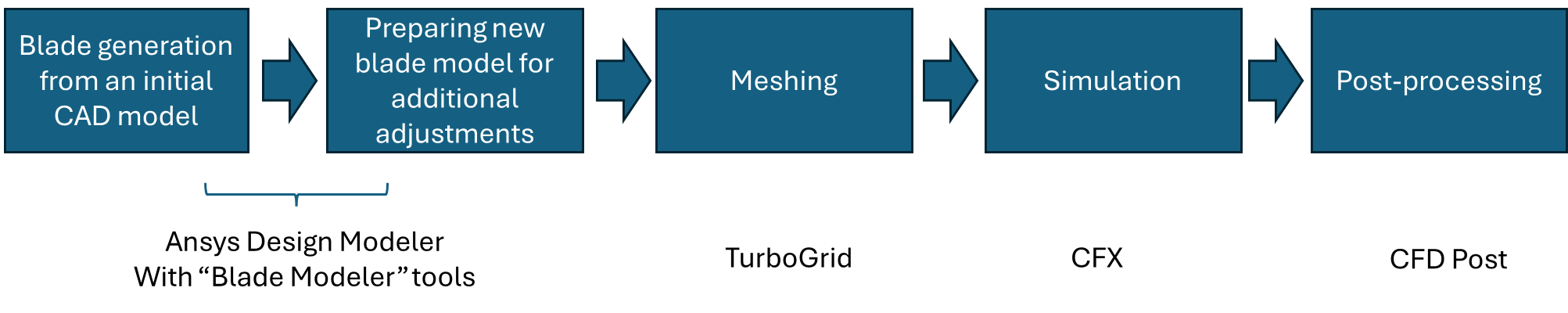
Figure 1. The Blade modeling workflow from the geometry generation to the simulation
The corresponding Workbench project may look like this (Figure 2):
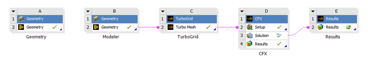
Figure 2. The Workbench project of the blade modeling workflow
There are several key actions to take in each step.
Step 1: Blade Geometry from CAD
Blade modeling from the initial CAD model requires working in the zx-plane view and creating sketches to describe the flow path.
Step 2: Trimming Fillets and Preparing Geometry
The fillets in the initial CAD model need to be removed when trimming the blade. The fillet will be added in the second geometry session, where the newly generated blade CAD file will be loaded.
Step 3: Blade Design Adjustments
The blade design, including the number of blades and blade profiles, can be adjusted in the second geometry session (Figure 3).
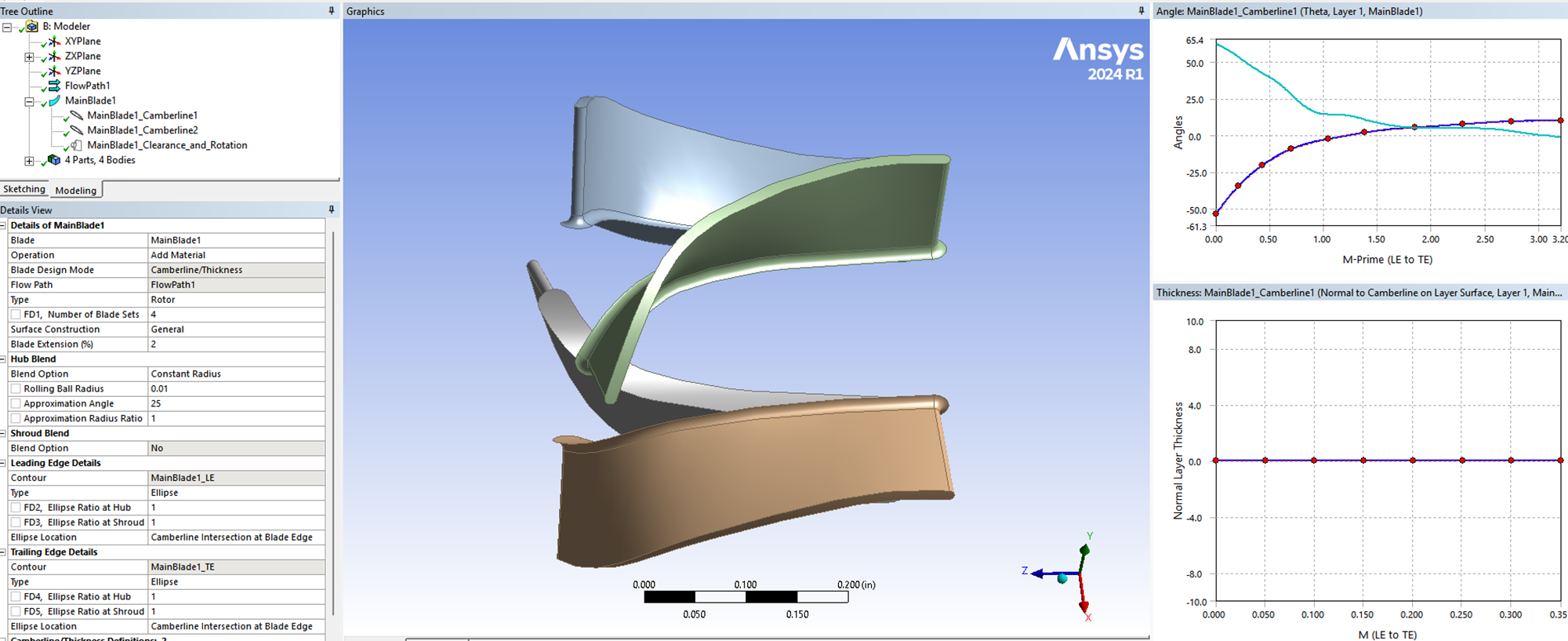
Figure 3. The blade design modifications
Step 4: TurboGrid Meshing
The TurboGrid session needs to be “updated” after connecting the Design Modeler. This will create an initial mesh structure, which can always be modified (Figure 4)
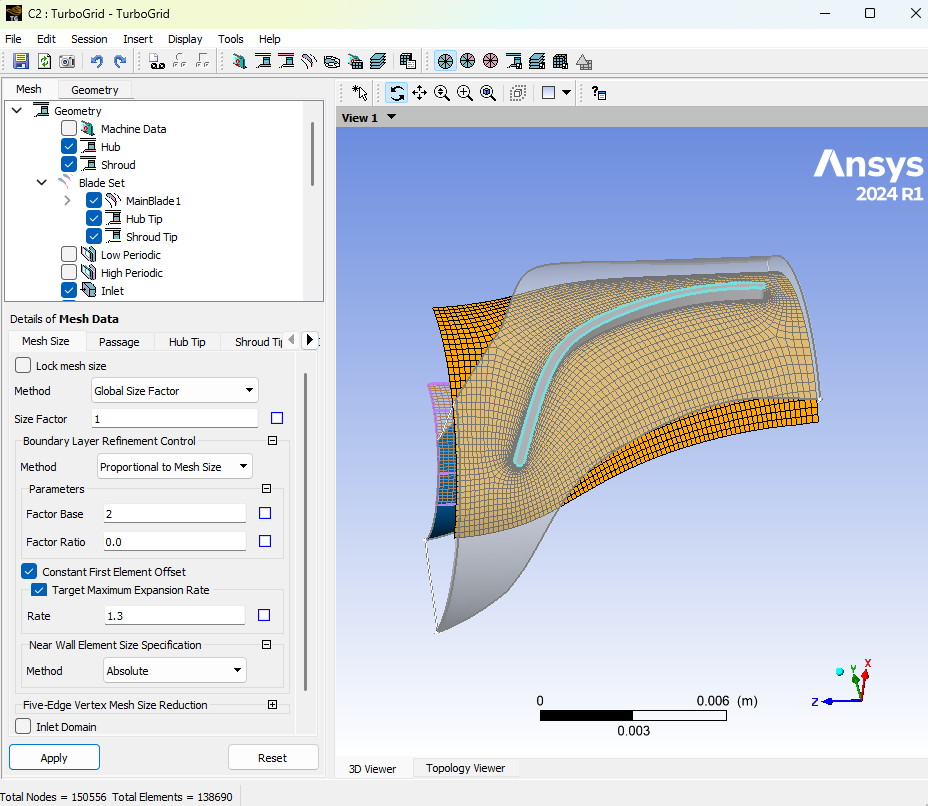
Figure 4. The TurboGrid session
Step 5: CFX Turbomachinery Setup
The “Turbo Mode” in the CFX session creates the turbomachinery model settings seamlessly (Figure 5)
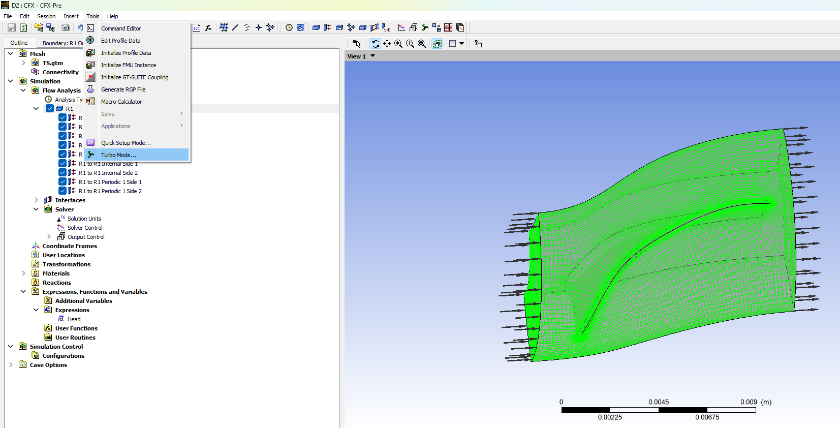
Figure 5. The CFX session
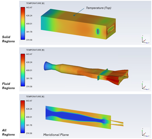
Step 6: Post-Processing with CFD-Post
The “Turbo” option in CFD-Post helps generate blade-to-blade views across different spans. Furthermore, additional instances can be added to achieve the model’s full 3D aspect.
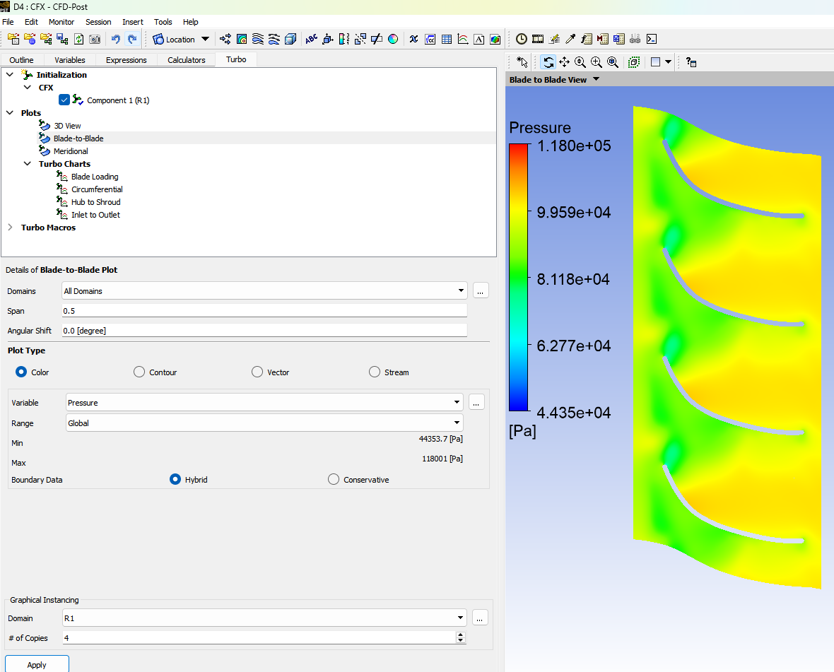
Figure 6. The CFD-Post session
Key Advantages of a Structured Blade Modeling Workflow in Ansys
Ansys has all the necessary tools for blade modeling.
Implementing a detailed and structured blade modeling workflow offers several benefits. Firstly, it enhances the design’s accuracy, ensuring the blade meets performance and reliability standards. Accurate modeling and simulation help in predicting real-world behavior, reducing the risk of failure.
Secondly, this workflow improves efficiency. By optimizing the meshing process and using advanced simulation tools, engineers can reduce the time and computational resources required, speeding up the development cycle.
Lastly, a robust blade modeling process supports innovation. With reliable simulation results, engineers can explore new designs and materials with confidence, leading to better-performing blades and competitive advantages in the market.
The details of the workflow can be found in the following YouTube videos:
Working on turbomachinery blade design or CFD simulation? SimuTech Group’s CFD consulting engineers work with Ansys CFX, TurboGrid, and the full turbomachinery suite. For more on our CFD capabilities, read our article on the evolution of user-friendly CFD in Fluent. Contact us to discuss your turbomachinery simulation needs.