Introduction to Bottom-Up Structuring in CMS
Let’s explore Component Mode Synthesis (CMS) in more detail. This method is also referred to as substructuring or superelements in other references. As the title suggests, we will focus on the Bottom-Up approach.
The Bottom-Up method received expanded support in the Ansys Mechanical and Workbench interfaces in the 2022 releases, making it easier than ever to apply CMS workflows to your models.
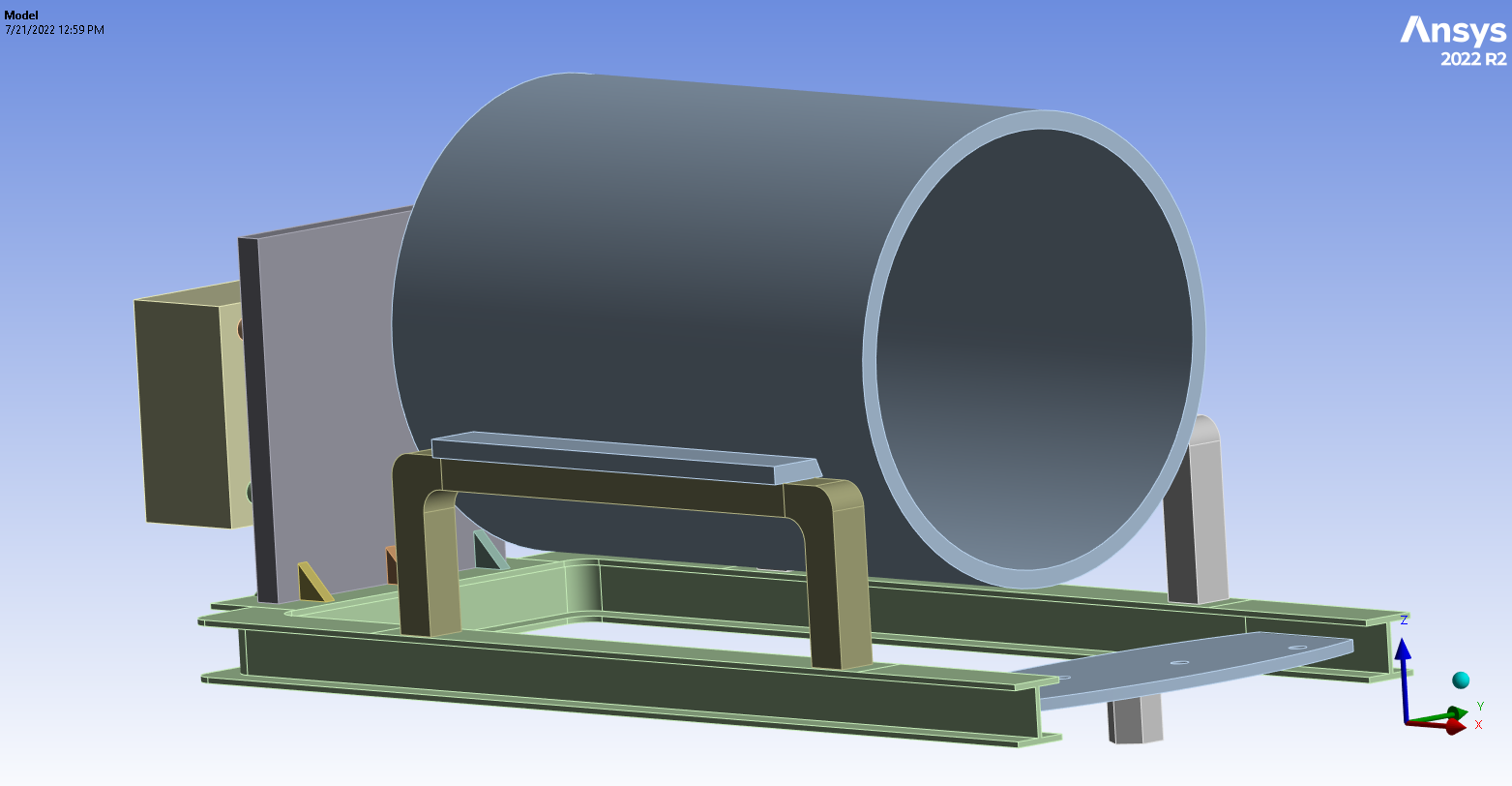
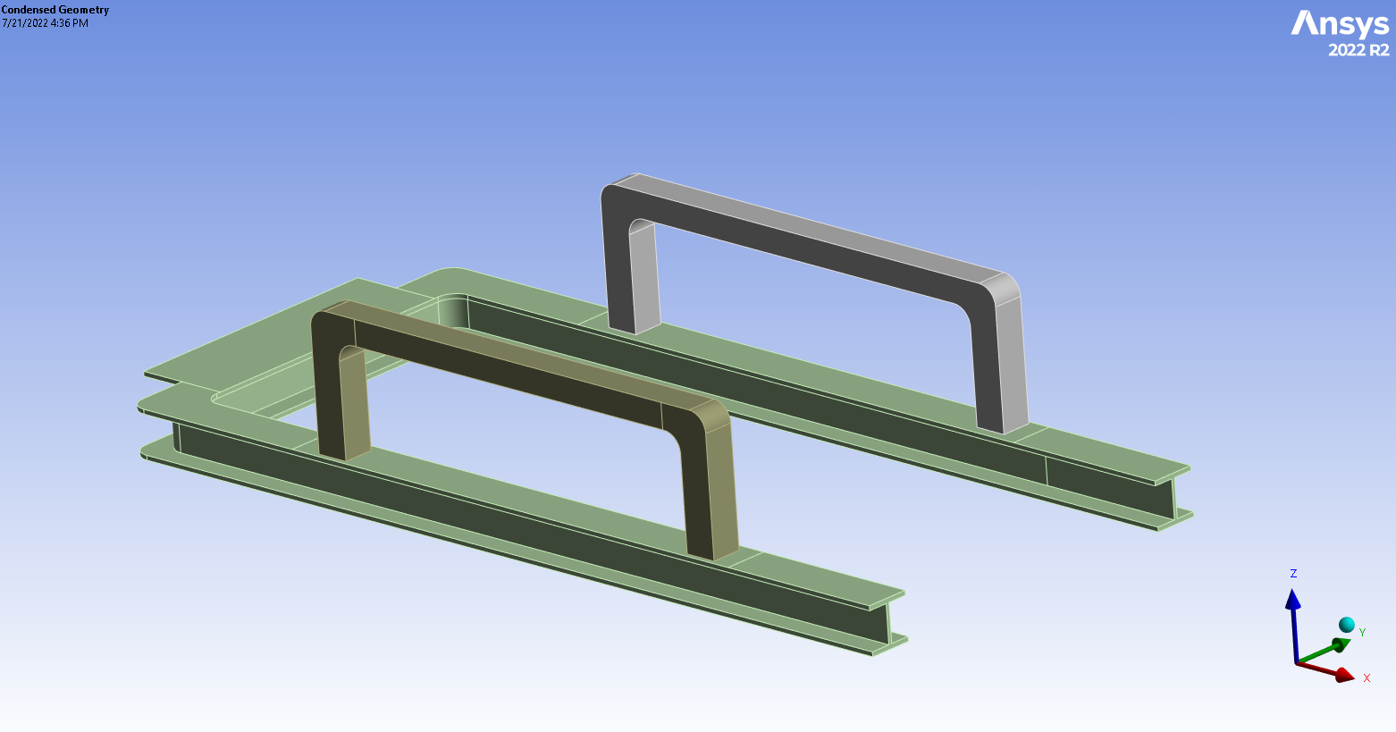
To begin, let’s introduce the assembly we will be working with. See the image of the full model below. This assembly will be substructured to reduce the computational intensity of the solve.
Substructure Generation
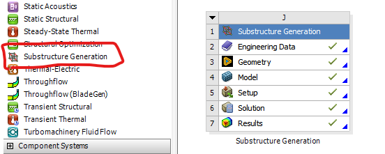
In 2022 R1, Ansys introduced the Substructure Generation analysis system into Ansys Mechanical. We will start by dragging it into the project area.
At this point, we can load our geometry through SpaceClaim or Discovery as we typically would for other analysis types. In this demonstration, we will generate a substructure for the large cylindrical object found in the assembly. For simplicity, we can import the entire geometry into SpaceClaim, Discovery, or Mechanical and suppress all components that we do not want to include in the substructure.
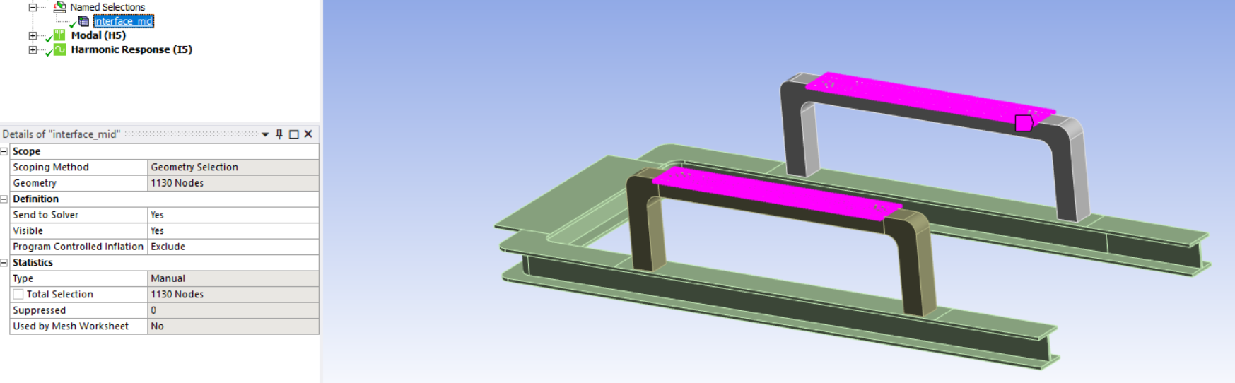
From there, we identify that the cylindrical object is connected to the rest of the assembly through the prismatic ledges on either side of the Y-axis. A named selection of the bottom faces of those ledges is created, renamed “interface_mid”, then dragged and dropped into the “Substructure Definition” object.
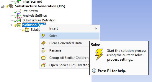
Notice how the named selection appears in the worksheet after being dragged into the Substructure Definition object. From there, we can solve the system. Ansys essentially performs a modal analysis of the substructure, with the named selection treated as a fixed boundary condition. For higher-frequency phenomena, it may be helpful to include more modes in the solution. This can be done under “Analysis Settings”.
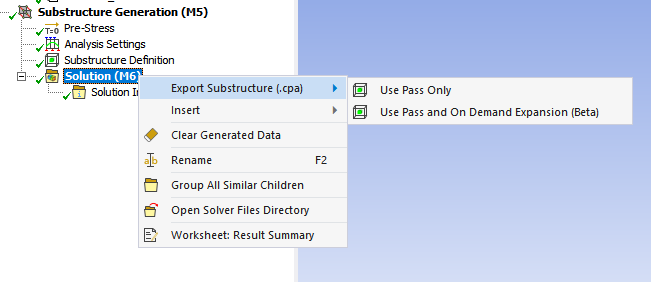
After the system is solved, we can export the substructure. If we right-click “Solution” and highlight “Export Substructure (.cpa)”, we are presented with two options: Use Pass Only and Use Pass and On Demand Expansion (Beta). The latter is helpful if the user wishes to evaluate deformation or strain quantities as part of the final analysis, but it requires substantially more disk space to save the .cpa file. Give the file a name and save it to a convenient location. In this example, it is named “middle.cpa”.
This completes the first leg of the workflow. This process should be repeated for each substructure the user wishes to include. In our case, this has been performed for the blocky posterior structure as well as the anterior plate found in the full assembly.
Condensed Geometry
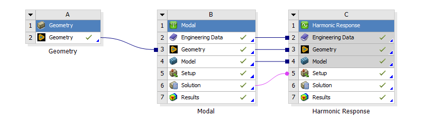
The next step is to create an analysis where the substructures will be imported. For this demonstration, we will use a Modal Analysis that is then fed into a Harmonic Response analysis. As before, we can import the full geometry and selectively suppress components. In this case, we have suppressed items that were converted into substructures. See above.
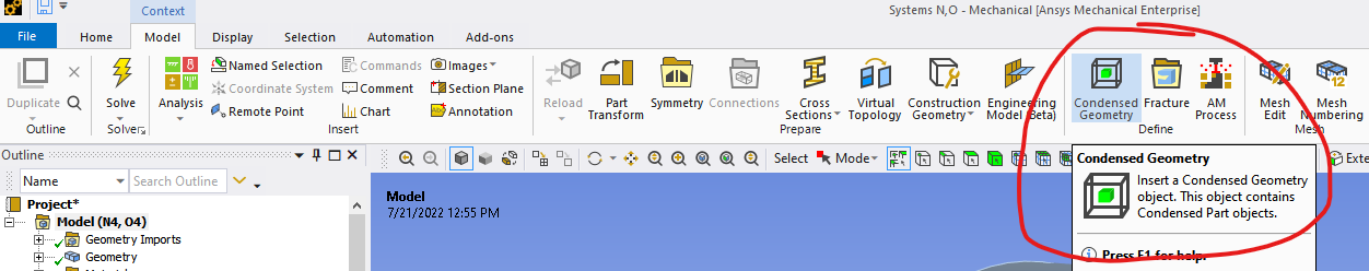
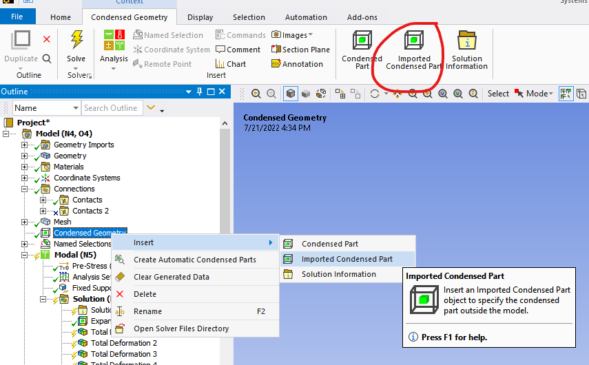
From there, insert a “Condensed Geometry” object into the model. Then, right-click on it and select Insert > Imported Condensed Part.
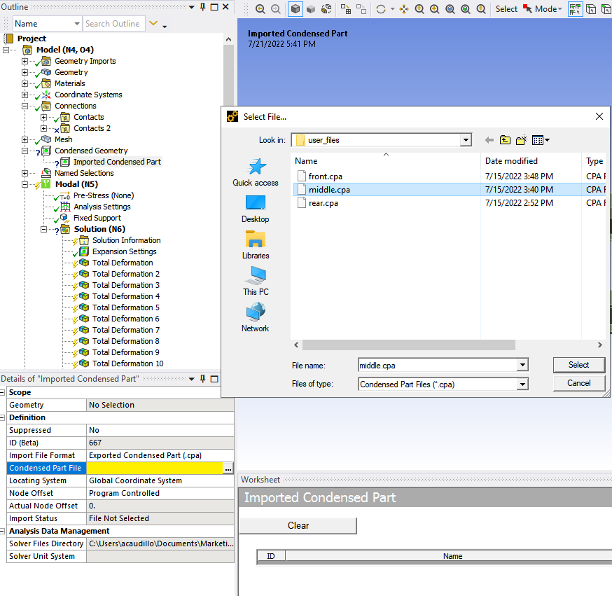
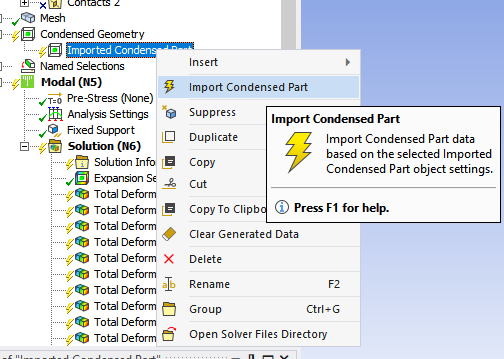
The details within the Imported Condensed Part show a yellow line indicating that user input is required. By moving the mouse over the field and clicking on the ellipses (…), a window opens that allows the user to navigate to the folder where the substructure file was saved and click Select. We can then right-click “Imported Condensed Part” and select “Import Condensed Part”. This process may take some time to finish, depending on the size of the substructure.
Ansys Mechanical returns a visual indicator of the substructure outlined in red when this process is complete.
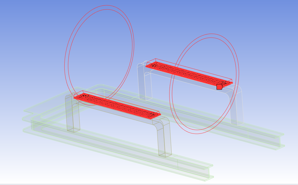
During the last step, Ansys also imports the named selection created in the Substructure Generation step as a nodal named selection into this model. In practice, this nodal named selection is used to attach the substructure to the rest of the model by creating bonded contacts.
As before, these steps are repeated for all substructures that need to be attached to the larger model. This completes the second leg of the workflow.
Result Visualization
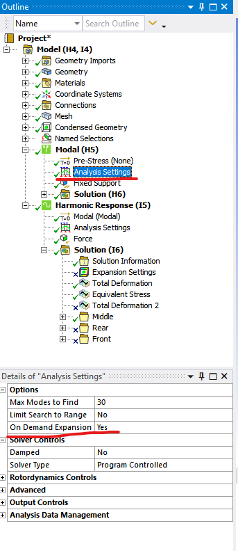
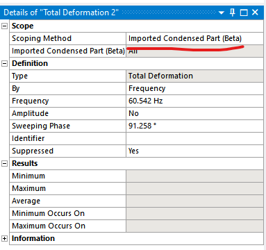
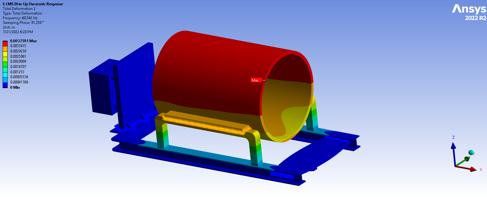
The same evaluation rules apply in the modal and harmonic response analyses regardless of the substructured geometries. If we selected the “Use Pass and On Demand Expansion (Beta)” option during the Substructure Generation portion, we can change the “On Demand Expansion” prompt to “Yes” in the Modal Analysis settings. Then, when viewing deformation results in the Harmonic Response analysis, we can select “Imported Condensed Part (Beta)” as the “Scoping Method”. This allows us to view the complete contour plot of deformation for the entire model, including substructures. As of the time of this writing, viewing contour plots for quantities such as stress is not supported.
After performing these model manipulations, what have we gained? To illustrate the difference, we performed the same analysis with the same geometry on two different models. The “Full Model” uses no substructuring or condensed parts; it is a direct analysis. The second model is the one we just built using Bottom-Up Substructuring. Both models produce similar results and show good agreement in their mode shapes and natural frequencies, as they should. Earlier, we stated that substructuring could reduce the computational effort of the solve. This is shown in the following table.
| Model | Time to Solve (from Solution Statistics) |
| Full Model (No Substructuring) | 5m 11s |
| Bottom-Up Substructuring | 19s |
Bottom-Up Structuring In Conclusion
Bottom-Up Substructuring helped cut solve time dramatically, reducing the analysis from more than five minutes to just 19 seconds in this example. While this approach requires more upfront effort during model setup, the time savings can quickly compound when analyses need to be rerun, refined, or reused across multiple design iterations.
For engineering teams working with large assemblies, repeated simulations, or computationally intensive models, substructuring offers a practical way to improve solve efficiency without sacrificing confidence in the results. If your team is looking to streamline complex Ansys workflows, SimuTech Group is here to help.