SynMatrix provides an efficient workflow for designing, optimizing, and fine-tuning filters across various topologies and frequency ranges, helping reduce design time while maintaining high performance.
In this blog, we demonstrate how SynMatrix is used to design a 5th-order coaxial cavity bandpass filter operating at 1 GHz. The process covers everything from the initial specifications to the final optimization.
Filter Synthesis: Defining Specifications and Coupling Matrix
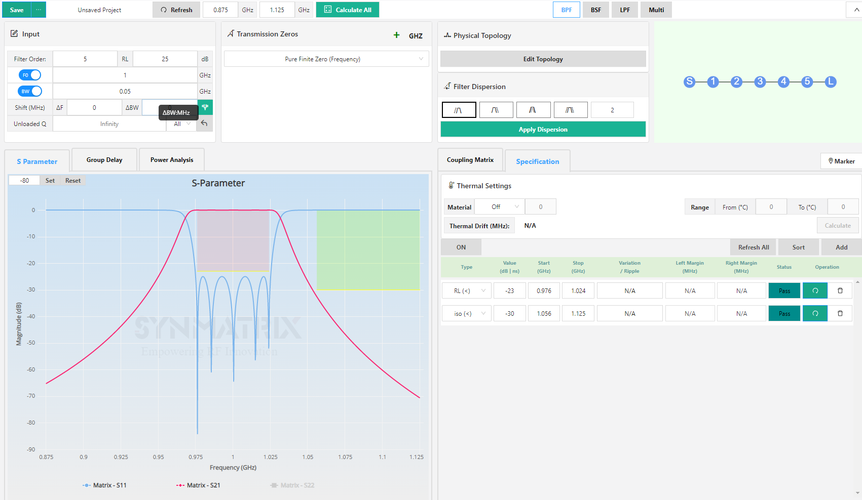
Begin the synthesis process by defining the filter parameters, such as order, return loss across the band, bandwidth, and other key specifications. In this example, the filter order is set to 5, with a return loss of 25 dB, a center frequency of 1 GHz, and a bandwidth of 0.05 GHz. No transmission zeros are added in this case, and the return loss and rejection requirements are specified as shown below.
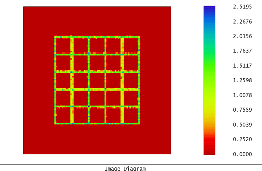
The coupling Matrix is:

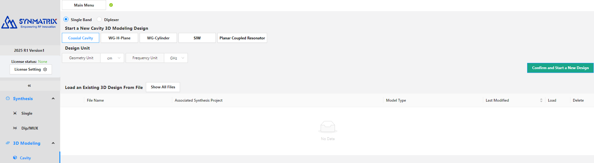
3D Modeling: Building the Coaxial Cavity Filter in SynMatrix
Navigate to 3D Modeling and select Cavity. You will see several options: coaxial cavity, rectangular waveguide, circular waveguide, SIW, and planar coupled resonator. Choose a coaxial cavity, then confirm and start a new design.
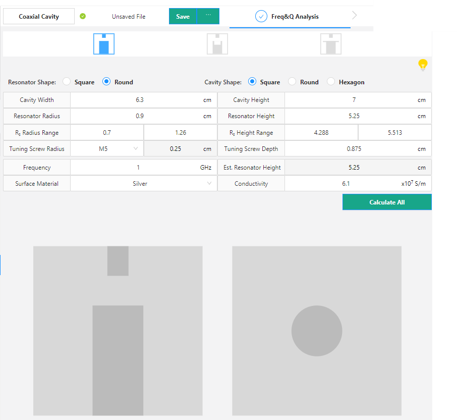
Step 1: Frequency and Q Analysis
For this filter, a flat-on-top configuration is used with the default dimensions applied:
Step 2: Single Cavity Configuration
The single cavity parameters are shown below:
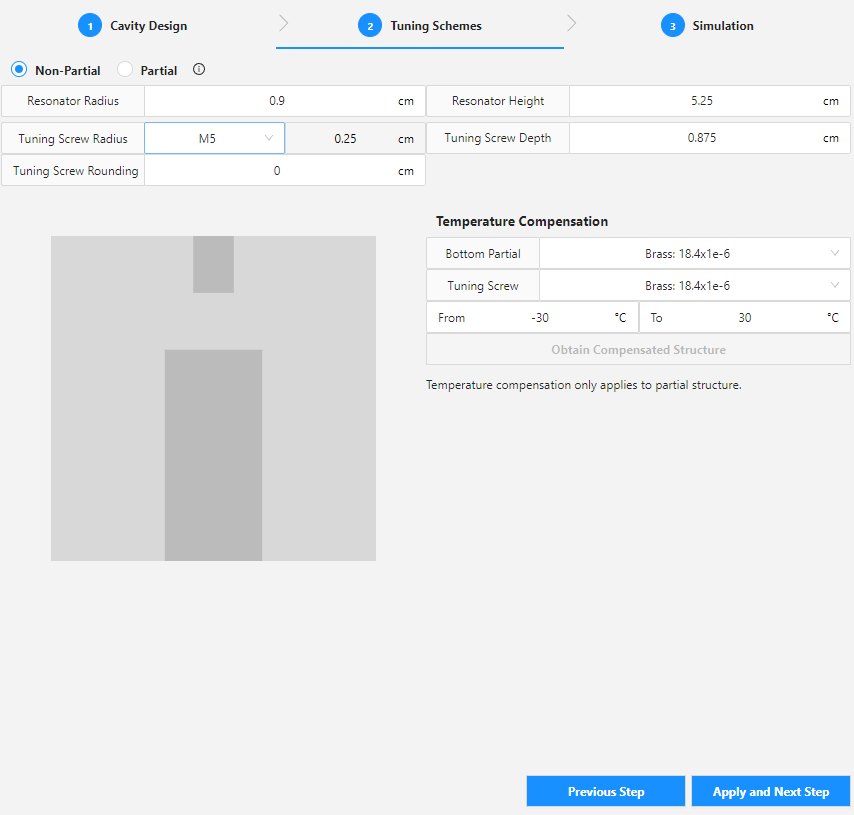
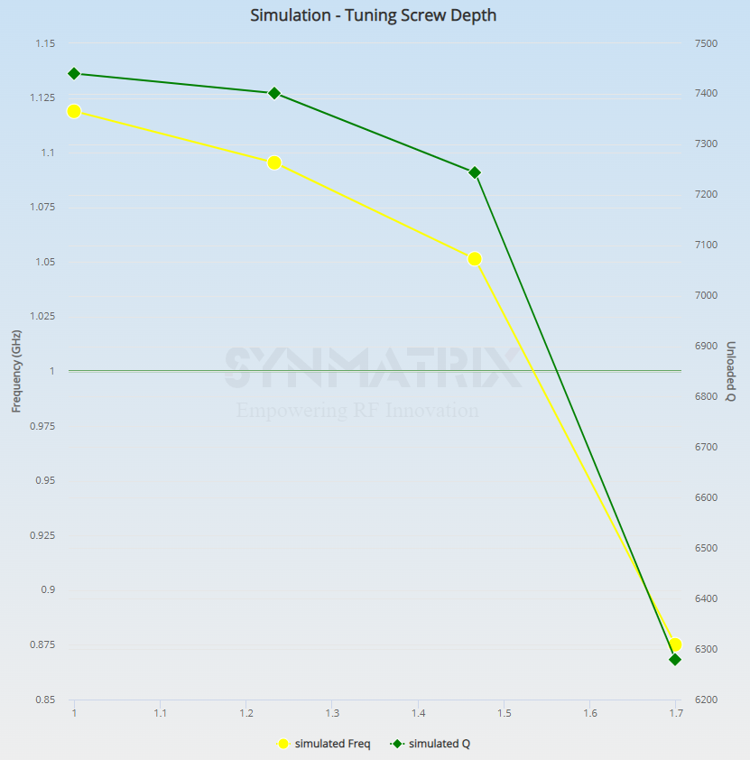
Based on the coupling matrix, the required resonant frequency for all resonators is approximately 1 GHz. A parametric sweep is performed for the tuning screw depth from 1 cm to 1.7 cm, and the estimated tuning screw depth for the target frequency is 1.54 cm.
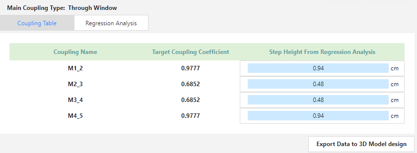
Step 3: Coupling Scheme
The through window coupling is selected as the main coupling method, as shown below:
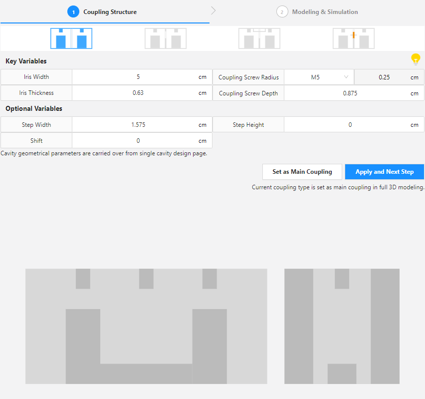
A parametric study of the step height is conducted from 0.2 cm to 1 cm, with the estimated values for each coupling shown below:
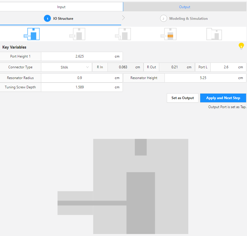
Step 4: Input / Output Configuration
A tap configuration is used for the input and output. The tuning screw depth is set to 1.589 cm.
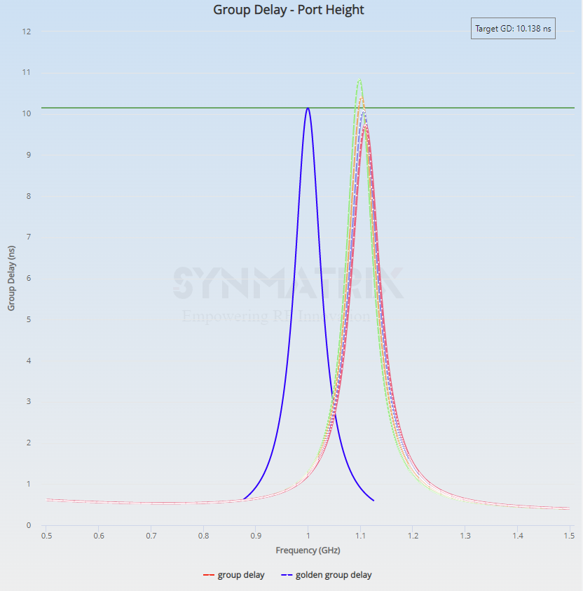
A parametric study is conducted for the port height, ranging from 2.4 cm to 2.7 cm. With a target group delay of 10.138 ns, the estimated optimal branch length is 2.5 cm.
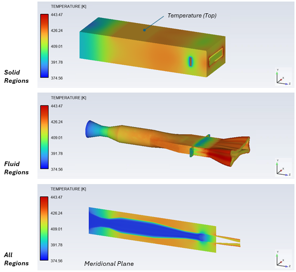
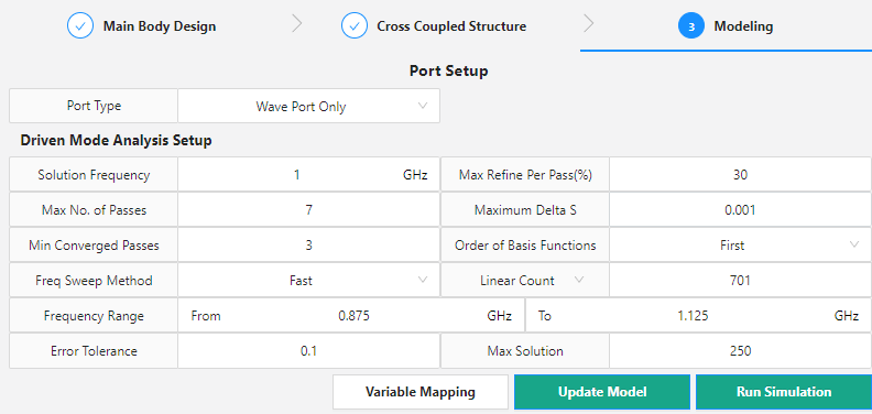
Step 5: Full 3D Model Assembly and Simulation
At this stage, all estimated values are applied to the main body design. Because this filter does not include a cross-coupled structure, that step can be skipped. The simulation setup is shown below:
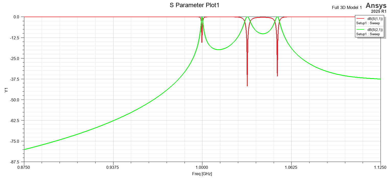
The initial filter response is shown below:
AI-Assisted Optimization and Final Filter Response
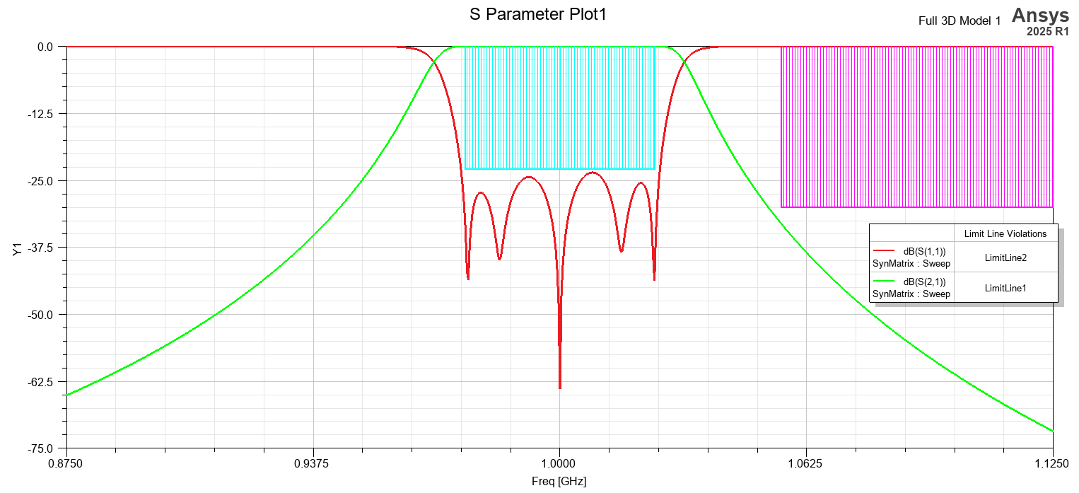
SynMatrix’s custom optimization and AI optimization are then used to tune and refine the filter. The final results are shown below:
The video below walks through all the steps in detail, and the filter model is available in the downloadable resources.
Designing RF cavity filters or working with SynMatrix for filter synthesis? SimuTech Group’s electromagnetic simulation consultants work with Ansys HFSS, SynMatrix, and the full RF design workflow. For more on antenna and RF simulation, see our article on antenna design using Ansys HFSS. Learn more about Ansys HFSS or contact us to discuss your project.