Thermal and Mechanical Challenges in Battery Cold Plate Design
Designing battery cold plates presents several challenges, primarily driven by the need to maintain optimal battery temperatures for performance, safety, and longevity.
One key challenge is achieving uniform cooling across all battery cells to prevent thermal imbalances, which can lead to degradation or failure. Space constraints within battery packs often limit the size and shape of cold plates, demanding highly efficient, compact designs. Material selection is also critical — designers must balance thermal conductivity, weight, corrosion resistance, and cost. Additionally, cold plates must withstand vibration and pressure variations in automotive or aerospace applications, requiring robust mechanical integrity. Manufacturing complexity, such as integrating microchannels for better heat transfer, adds to cost and design constraints. Finally, the cold plate must integrate seamlessly with the broader thermal management system, including pumps and heat exchangers, while meeting regulatory standards. These factors make cold plate design a multidisciplinary challenge involving thermal, mechanical, and systems engineering.
Common Engineering Approaches to Cold Plate Cooling
Typical engineering solutions for battery cold plate challenges focus on maximizing thermal performance while minimizing space and weight. Microchannel designs are commonly used to increase surface area and enhance heat transfer efficiency. High-conductivity materials such as aluminum or copper are selected for their ability to quickly dissipate heat. Engineers often employ computational fluid dynamics (CFD) to optimize coolant flow paths and ensure uniform temperature distribution across all battery cells. To address space constraints, cold plates are designed with thin, compact geometries that can be tightly integrated into battery modules. Leak-proof sealing methods and corrosion-resistant coatings improve durability and system reliability. Additionally, cold plates are often designed as part of an integrated thermal management system that combines pumps, sensors, and heat exchangers for precise temperature control.
Why Ansys Discovery CFD Accelerates Cold Plate Design
ANSYS Discovery CFD simulation offers fast, interactive tools that help engineers explore and validate thermal and fluid design concepts early in the development process. For battery cold plates, it enables real-time simulation of coolant flow and heat transfer, helping optimize microchannel geometry, flow paths, and material choices. With its intuitive interface, engineers can quickly modify designs and instantly see the effects on temperature distribution and pressure drop. This accelerates the design cycle and reduces the need for physical prototypes. Discovery also supports multiphysics simulations, allowing integration of thermal, fluid, and structural analyses. This helps identify potential issues like hotspots, flow imbalances, or mechanical stresses, enabling more robust, efficient, and cost-effective thermal management system designs.
Simulation Setup: Thought Map, Product Map, and Discovery Configuration
Setting up a battery cold-plate simulation in Ansys Discovery involves several steps. These steps include the thought map, product map, and the Discovery case setup.
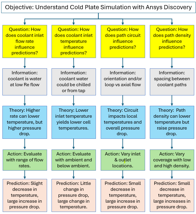
Thought Map
A thought map of modeling characteristics is generated to organize and represent ideas, concepts, or information in a structured way. The thought map below shows the simulation study’s objective and the questions asked to address it. Each question is followed by a theory, an action, and a prediction. Results would also be added to the bottom of each branch as they are generated.
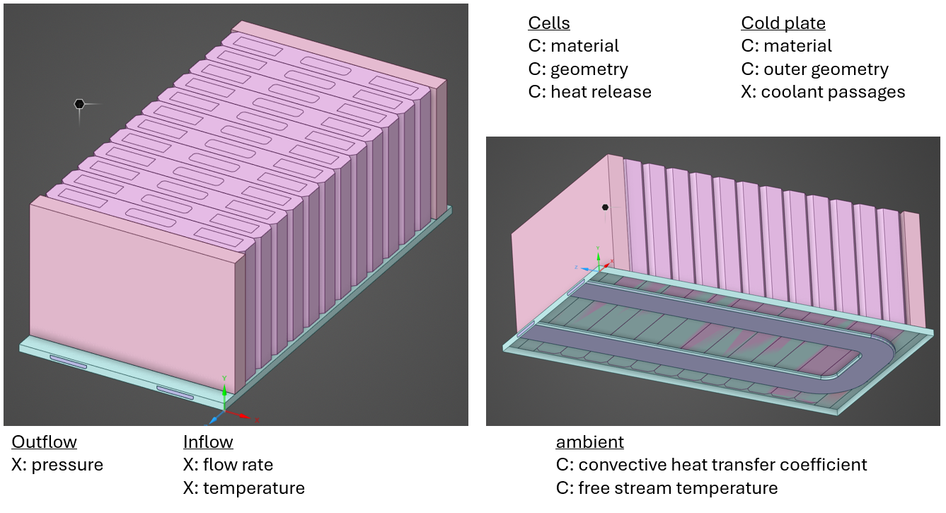
Product Map
A product map of the battery cold plate is generated to list and categorize product features. A product map indicates constant factors (C) and some variable factors (X) that correspond to theories/actions in the thought map.
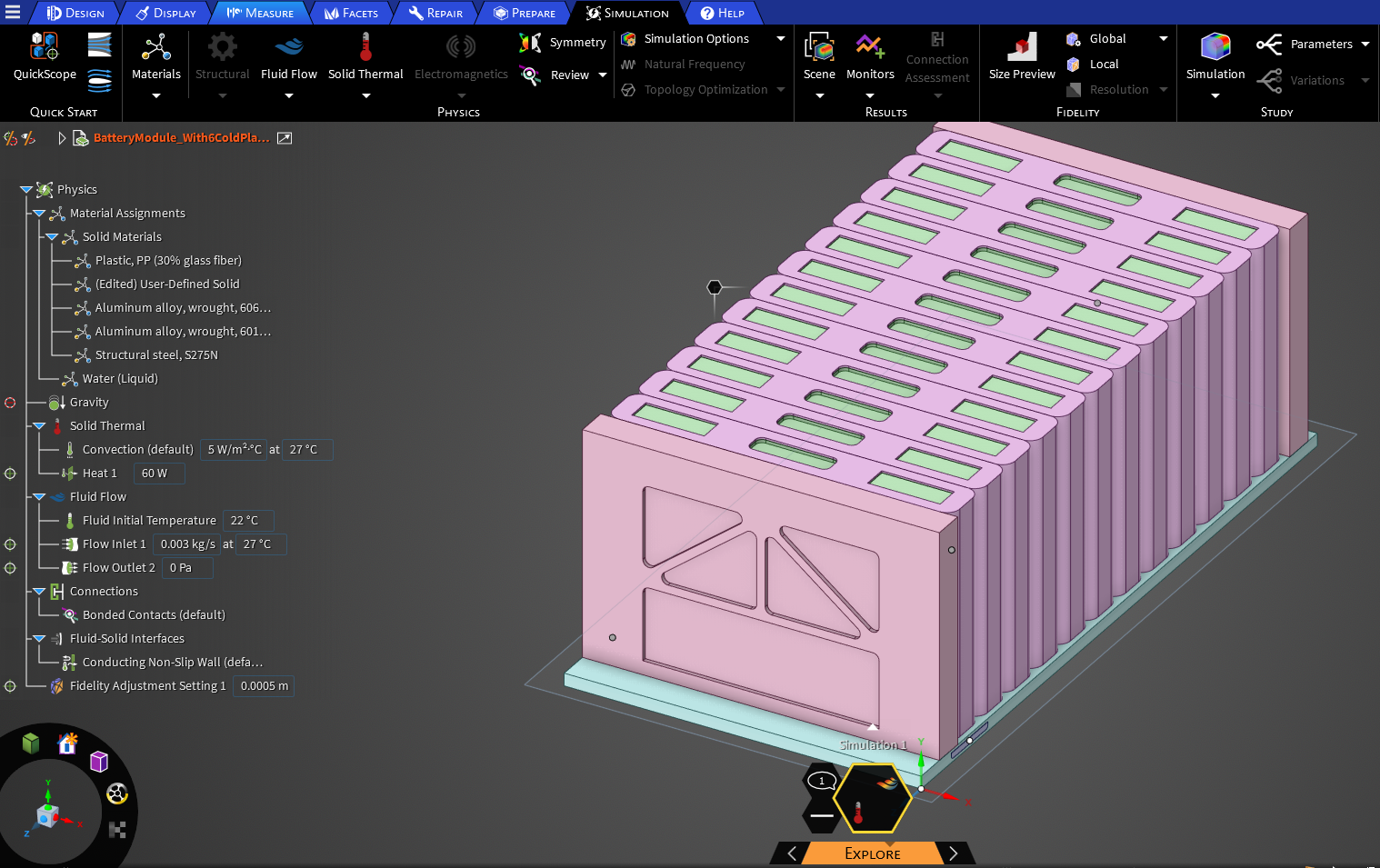
Ansys Discovery Simulation Setup
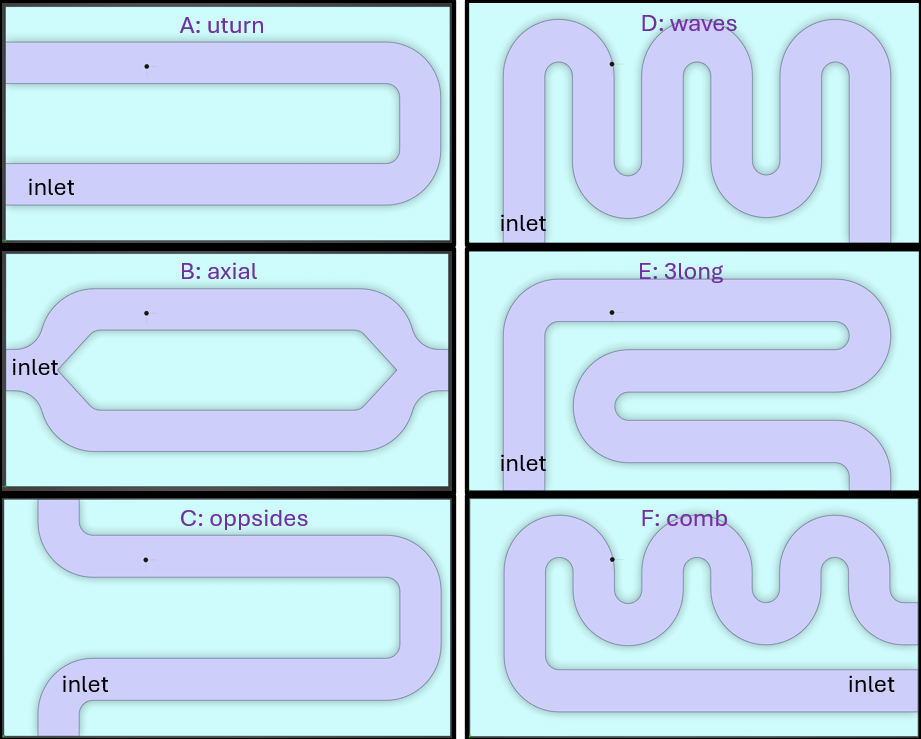
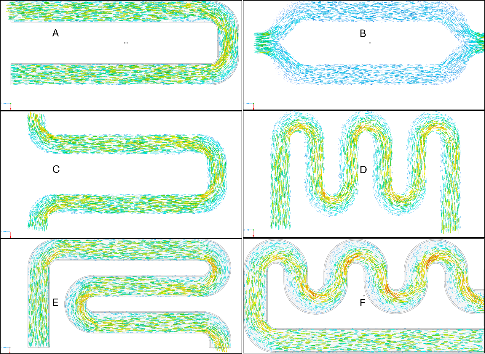
Discovery models are set up to address the questions and geometry addressed by the thought map and the product map. Below are 6 concepts of the coolant path used in the steady-state calculations.
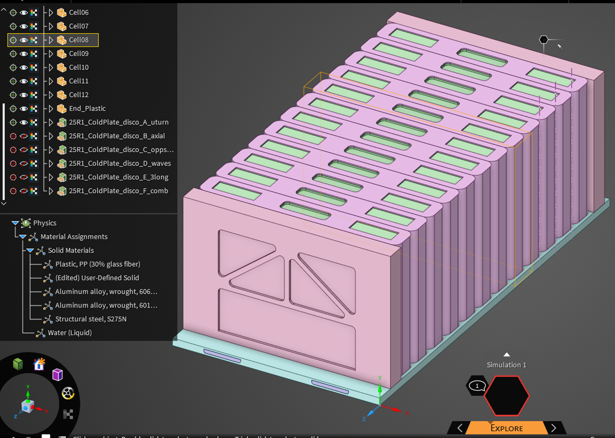
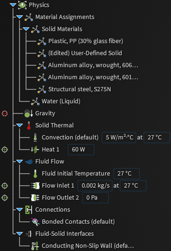
Physics – Material Assignment
- End plates are assigned with plastic material.
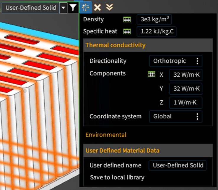
- Cells are assigned with a new user-defined material
- Cold plate and cell shells are assigned with aluminum material.
- The coolant path is assigned with liquid water material.
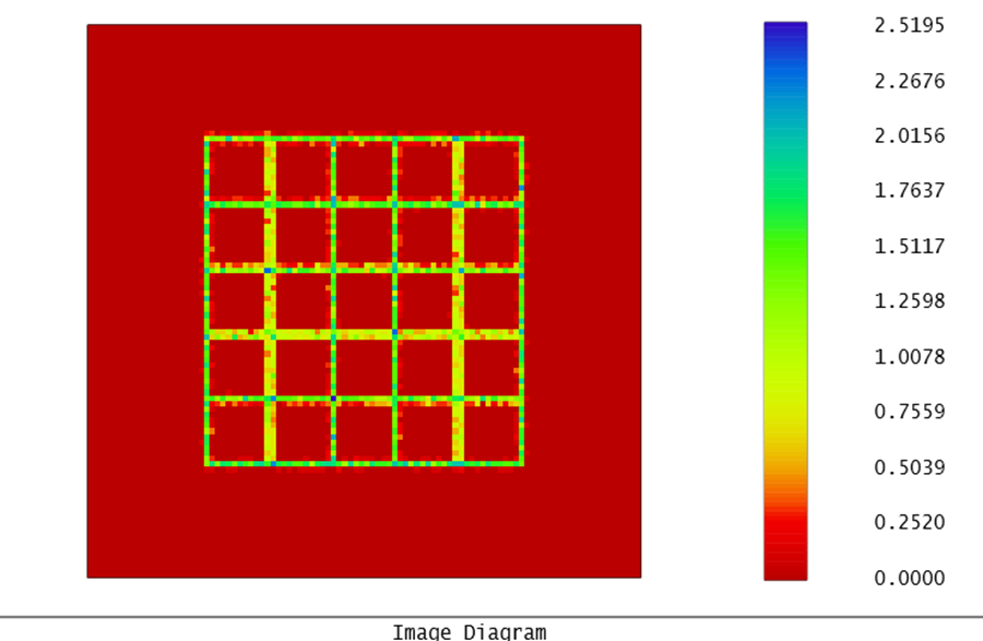
The user-defined material for the cells includes an orthotropic thermal conductivity.
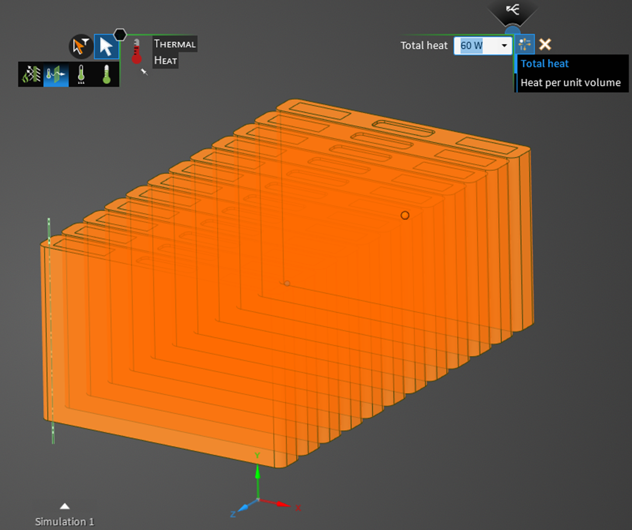
Physics – Solid Thermal:
- A total heat source of 60 Watts is set for the cells.
- External walls are set to a convection boundary condition with a heat transfer coefficient of 5 W / (m^2 K) and a free stream temperature of 27 C.
- Bonded contact connections are automatically created.
Physics – Fluid Flow:
- Inlet is set to the coolant inlet, with flow rates of 1 g/s or 3 g/s and a temperature of 23 or 27 °C.
- The outlet is set as an outflow with a gauge pressure of 0.0 Pascal.
- Conducting no-slip walls are automatically generated at fluid-solid interfaces.
- An initial fluid temperature of 23 or 27 C is set.
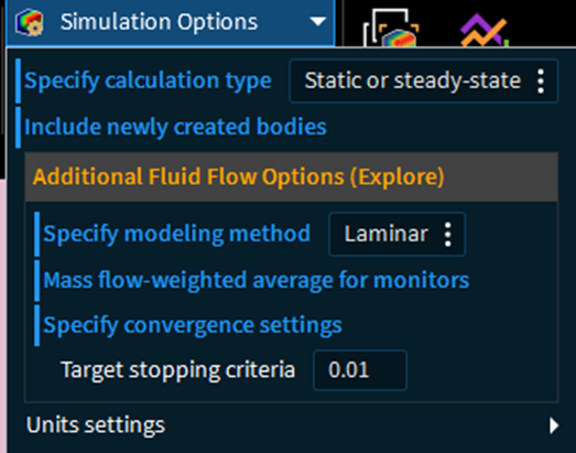
Physics – Fluid Flow:
- The static /steady-state calculation type is specified.
- The laminar modeling method is specified.
- Mass flow-weighted average for monitors is specified.
- Stopping criteria of 0.01 are specified.
Fidelity:
- Global fidelity of 66% is used for the mesh.
- Local fidelity of 0.5 mm is used for the fluid zone surfaces mesh.
Simulation Results: Comparing Six Cold Plate Concepts
Influence of Coolant Flow Rate and Inlet Temperature
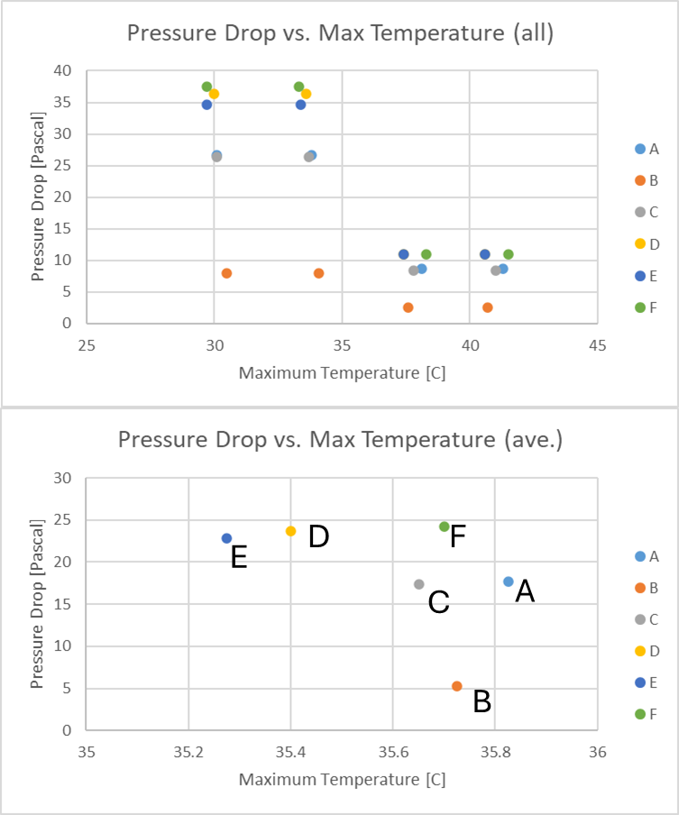
Increasing the coolant inlet temperature from 23 to 27 degrees C yielded an average increase of 3.4 degrees C in the maximum temperature. Increasing the coolant flow rate from 1 to 3 grams/second decreased the maximum temperature by an average of 7.5 degrees C. Increasing the coolant inlet temperature from 23 to 27 degrees C had a negligible influence on the pressure drop. Increasing the coolant flow rate from 1 to 3 grams/second yielded an average 3.3-fold increase in pressure drop.
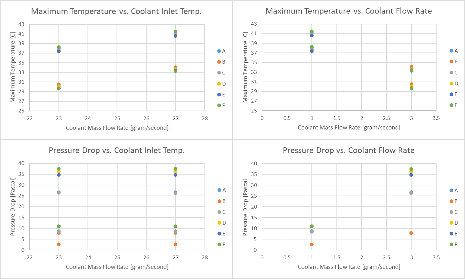
Trade-Off Between Maximum Temperature and Pressure Drop
Data from 24 runs are plotted for each concept as a group. All four runs for a concept have the same color. The data indicate that the maximum temperature ranges from about 30 to 41 degrees C. The averages for each concept are in the following graph. Concept E had the lowest maximum temperature; however, it had one of the highest pressure drops. Concept B had the lowest pressure drop; however, it had one of the highest maximum temperatures.
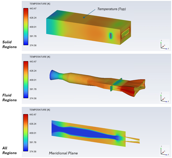
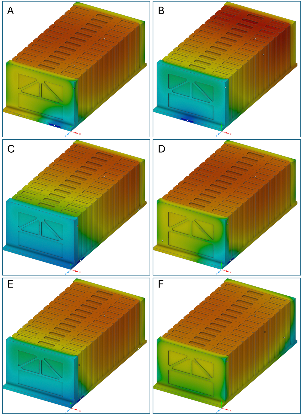
External Temperature
Contours of the battery’s external temperature from 27 to 34 degrees C are plotted for each concept in the “home” view. The influence of coolant inlet and outlet locations on temperature distribution is visible.
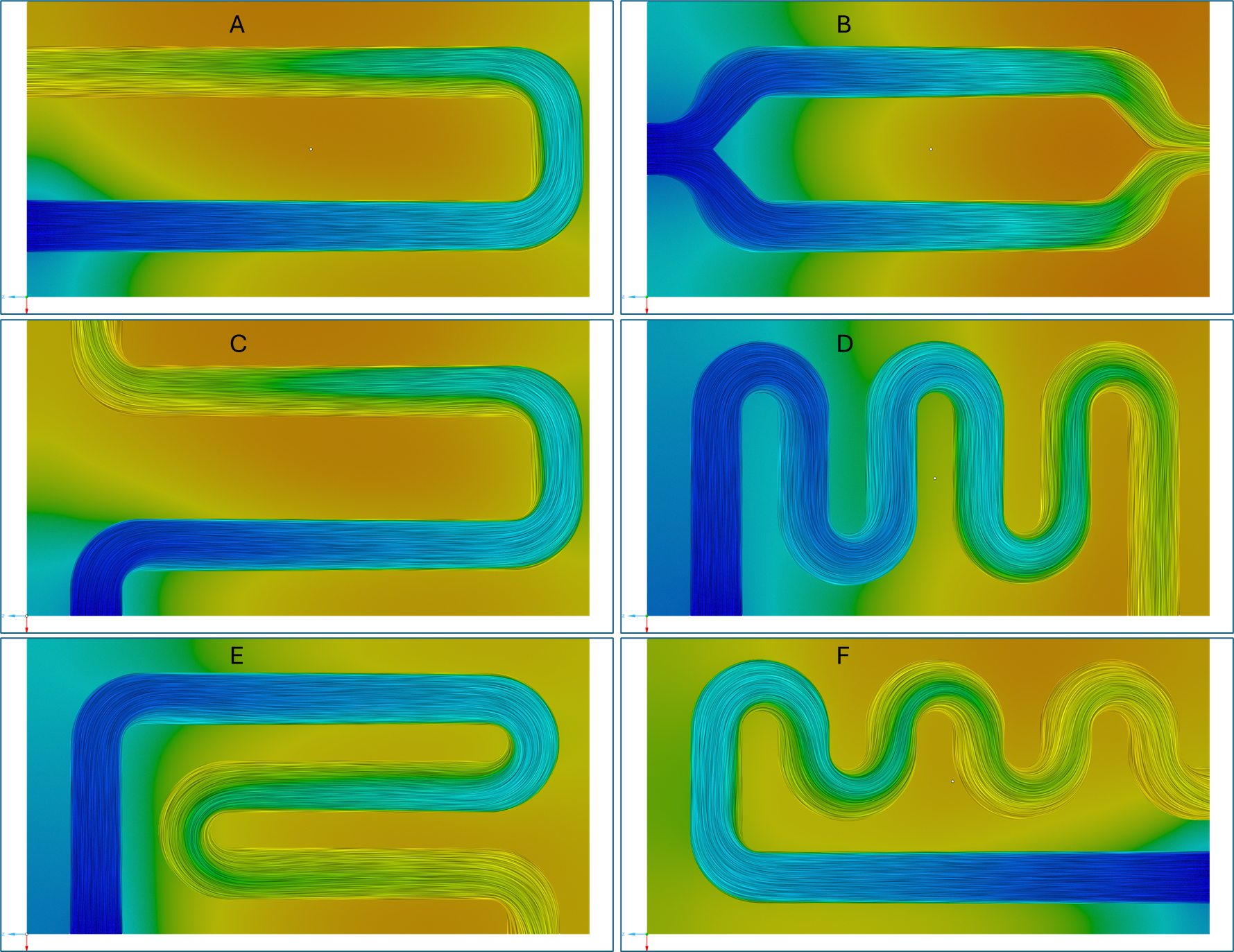
Coolant Temperature
Contours of coolant and cold plate temperature from 27 to 34 degrees C are plotted for each concept in top view. The influence of coolant inlet and outlet locations on temperature distribution is visible.
Coolant Pressure
Streamlines of coolant total pressure from 0 to 37.5 Pascals are plotted for each concept in top view. The influence of the coolant path on the pressure distribution is visible.
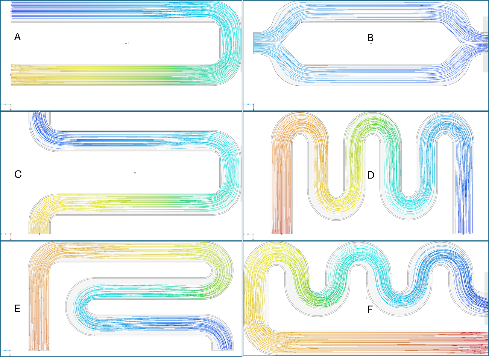
Coolant Velocity
Vectors of coolant velocity from 0 to 0.08 m/s are plotted for each concept in top view. The influence of the coolant path on the velocity distribution is visible.
Video
The following video highlights the setup steps using Ansys Discovery.
How Ansys Discovery Fits into the Broader Battery Design Workflow
Ansys offers advanced capabilities for simulating battery cold plates, which offer numerous benefits, including enhanced design optimization, improved reliability, and cost savings. By accurately predicting battery cold plate performance, manufacturers can design products that meet specific requirements more efficiently.
Ansys Discovery enables the rapid evaluation of multiple design/input factors such as fluid inlet temperature, flow rates, and cooling path geometry. A design engineer can evaluate multiple design options to understand the flow behavior. Beyond Discovery, Ansys provides tools such as CFX, Fluent, LS-Dyna, DesignXplorer, OptiSLang, and Mechanical for further design parametrization and evaluation.
Exploring battery cold plate concepts or comparing cooling path designs? SimuTech Group’s CFD and thermal consulting engineers work with Ansys Discovery, Fluent, and the full thermal management simulation suite. For more on battery thermal simulation, see our article on SVD reduced order models for battery module thermal analysis. Learn more about Ansys Discovery or contact us to discuss your project.