Introduction
Modern communication systems integrate resistive, capacitive and inductive (RLC) networks with active components like transistors and diodes to create sophisticated integrated circuits (ICs). In this environment, RLC circuits serve as critical building blocks for filters, amplifiers, oscillators, and matching networks, and their performance is dictated by precise resonance and damping characteristics.
To ensure the high-fidelity performance of designs, meticulous modeling of these passive elements is often necessary. Ansys HFSS facilitates this by enabling the simulation of discrete resistors, capacitors, and inductors directly within a full 3D electromagnetic environment using several specialized modeling techniques.
Overview
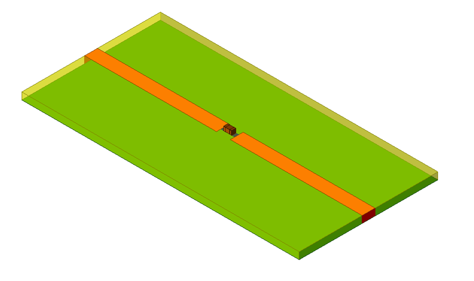
In this blog, we explore the various methodologies for modeling lumped components within Ansys HFSS. We will demonstrate how to scale the complexity and fidelity of your models—ranging from basic idealizations to high-accuracy representations—ensuring your simulation strategy aligns with both your specific application frequency and the physical characteristics of the components used. Below is a microstrip line with inserted 0201 size capacitor to modeled directly with Ansys HFSS.
Modeling Lumped Components in Ansys HFSS
HFSS allows the simulation of lumped components using 3 approaches; 1) lumped RLC boundaries, 2) lumped ports, and 3) directly attaching S parameters files.
Lumped RLC Boundaries
To model any combination of lumped resistor, capacitor, and inductor whether in parallel, series, or a combination on a PCB, the user can create a lumped RLC boundary that represents any of these cases. Similar to impedance boundaries, the following equation holds at lumped RLC boundaries. However, the user doesn’t need to enter the impedance per square. HFSS performs these calculations based on the provided R, L, and C values at any frequency.

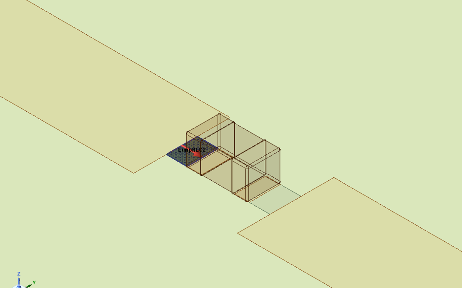
To assign this boundary, the user needs to create a rectangular face, assign the RLC type, and define the current flow line to specify where on the surface the current and voltage will be controlled. Non-rectangular faces can be used, however, it can result in a less accurate representation of the lumped component. The R, L, and C values can all be defined to include the parasitics associated with the component of interest. Below is a representation of the added series Lumped RC boundary to model the capacitor.
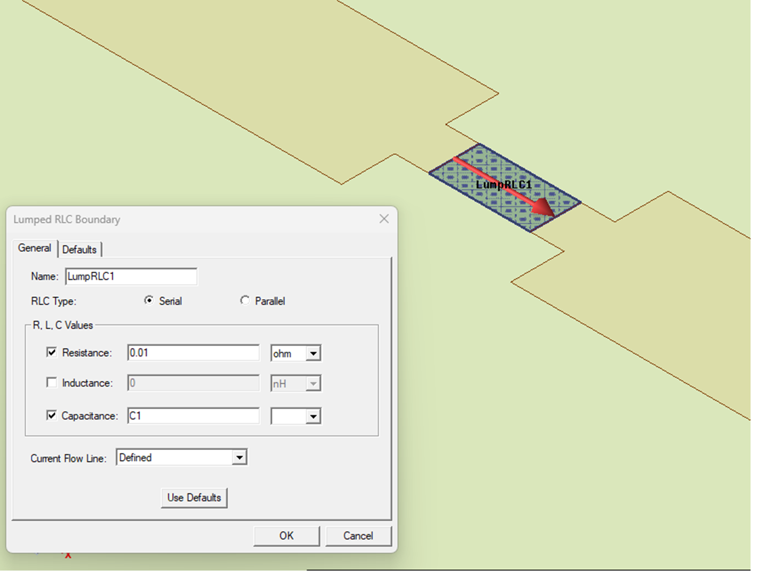
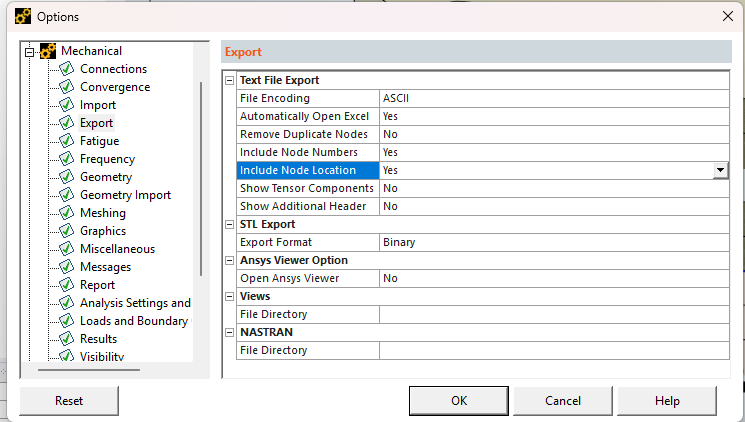
As can be seen, the capacitance value can parameterized. These values can then be optimized using Optimitrics to meet the response requirements without the need to re-generate the mesh. HFSS allows the solve with copied mesh from a geometrically equivalent model.
To increase the accuracy of simulation, the lumped component geometry can also be modeled. For example, for high frequency applications, depending on the size of the component used, additional parastics can be caused by the direct coupling between the component geometry and the PCB traces. The RLC boundary can be adjusted to account for the addition of the component geometry. In the below example in Figure 3, the RLC boundary has been divided into 2 series sections, and the R,L, C values have been adjusted.
Lumped Components in Ansys HFSS: Ports and Circuit
Another approach to simulate a lumped component is by placing a lumped port at the component location and then perform circuit simulation based on the generated EM results. The advantage of this approach is that only one HFSS simulation will be needed. A circuit analysis linked to these HFSS results can be quickly performed for any combination of RLC values. This can be done by placing a single horizontal port between the pads where the lumped component will be connected or with 2 vertical ports, as seen below. Both approaches should provide similar results.
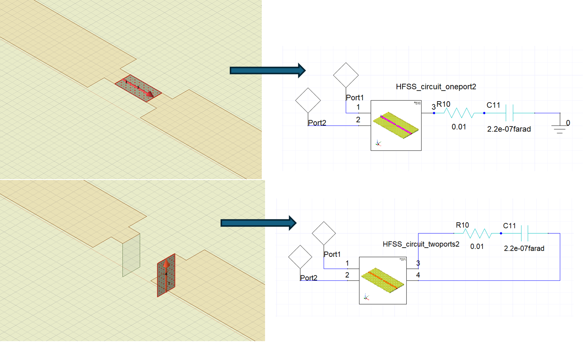
In Ansys Electronic Desktop (AEDT), Ansys HFSS designs can be dynamically linked into Ansys circuit tool to accelerate the design process and increase the design flow power and flexibility. To link the HFSS design into circuit, the user can drag and drop the HFSS design into the circuit, after which the HFSS-extracted model will appear as a component in the schematic. This link enables the users to add circuit elements including active circuitry and run different types of analyses. This link allows the user to observe the impact of added circuit elements on EM results in HFSS such as near and far field data by “pushing the excitations” from Circuit to HFSS.
Adding TouchStone Files
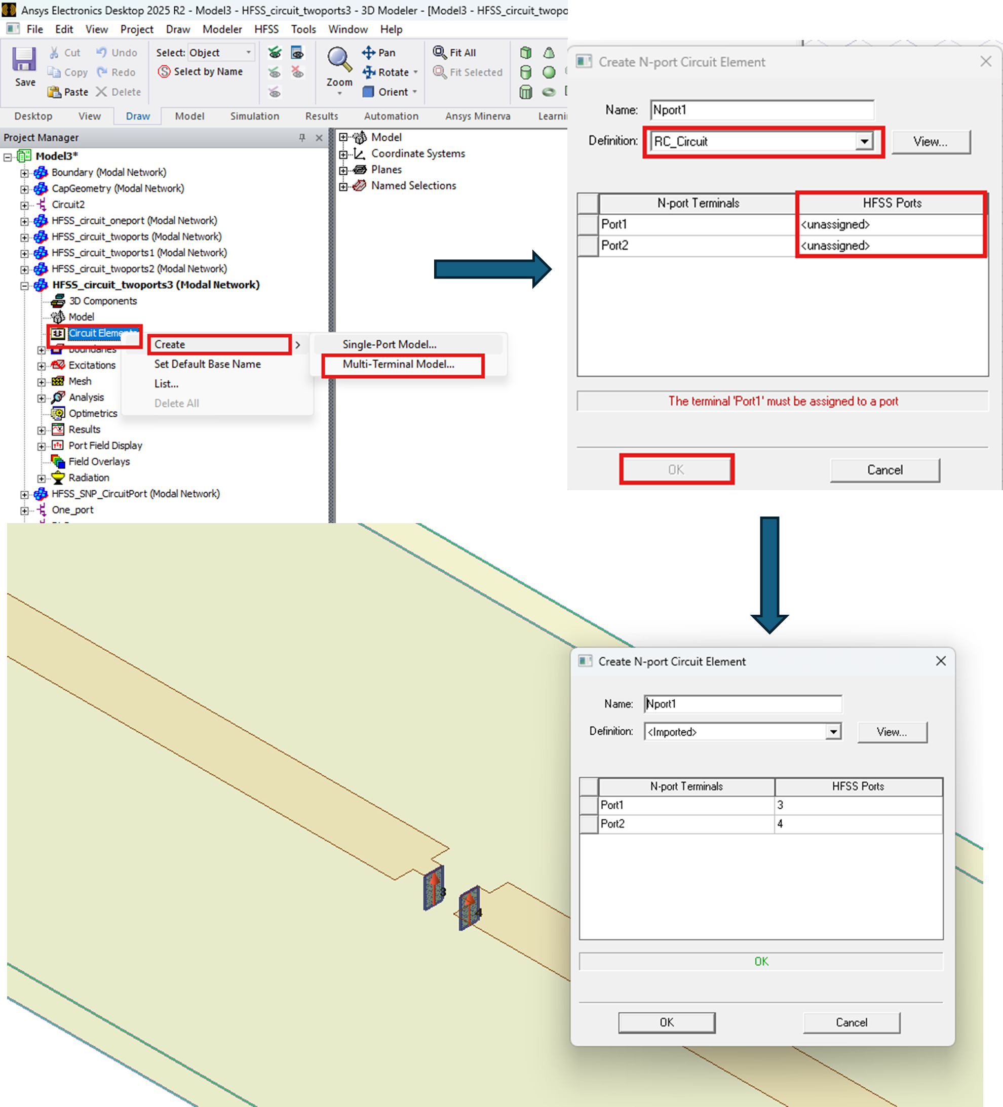
HFSS allows the users to add touchstone files (snp) that represent the behavior of the lumped components. These files can be based on circuit modeling or measurements. These files can be imported and assigned to defined HFSS ports. The user can import different libraries from vendors as well. In the 2026R1 release of the electronics desktop, adding s-parameters of active elements such as LNAs or power amplifiers, was enabled as well. Figure 5 shows the few steps needed to add a touchstone file to model the capacitor behavior.
Comparison
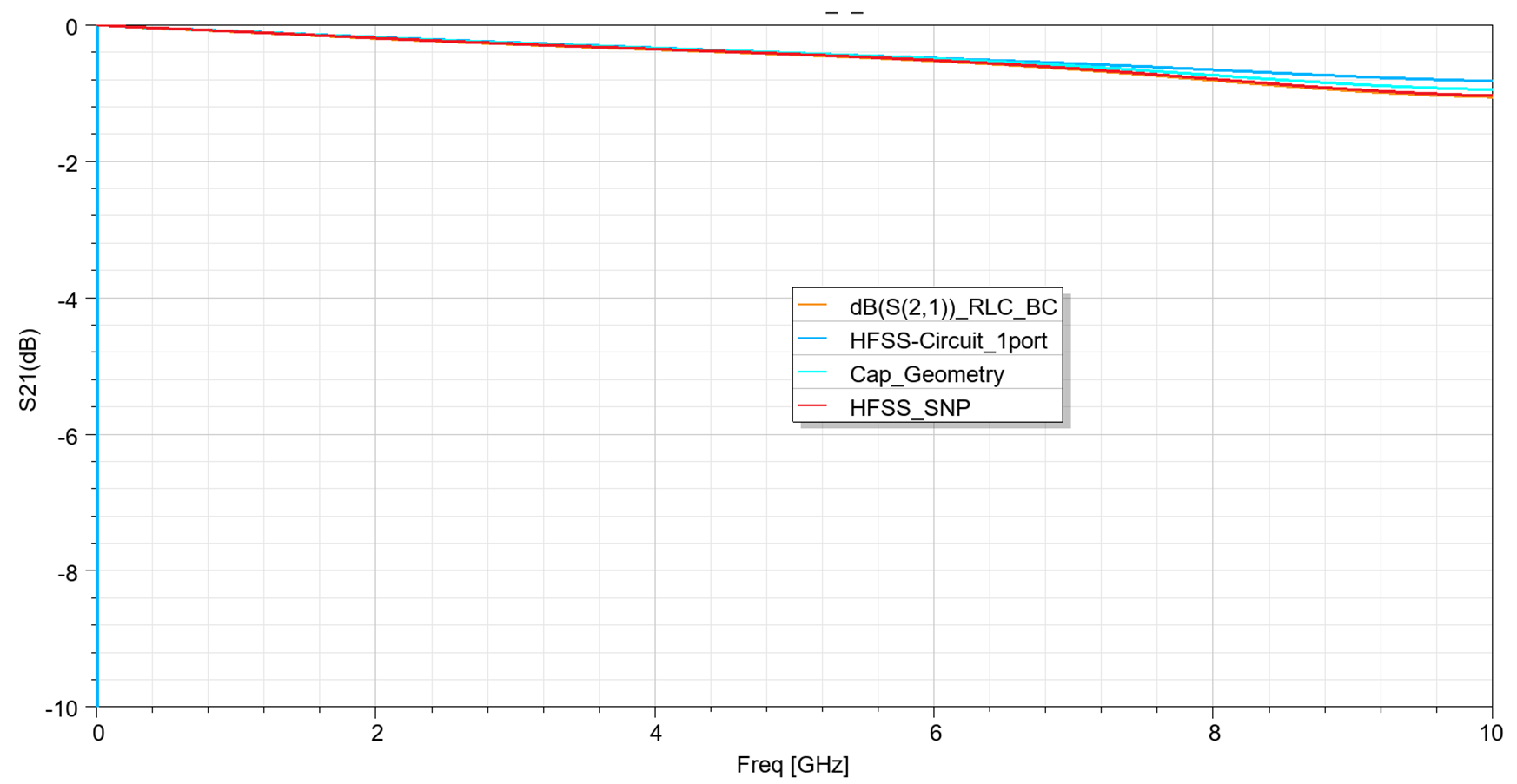
Below is a comparison of the simulation results of an actual capacitor for the different approaches presented. As seen, the results are in good agreement. The differences we see at higher frequencies are expected due to the different models and methods used which provide different levels of accuracy depending on the application and the details included.
Modeling Lumped Components in Ansys HFSS: In Conclusion
Modeling lumped components in Ansys HFSS gives engineers the flexibility to choose the right level of detail for their application. Lumped RLC boundaries offer a fast and efficient way to represent passive components, lumped ports with circuit links allow rapid evaluation of different RLC values, and Touchstone files provide a practical path for incorporating measured or vendor-supplied component behavior.
By selecting the appropriate modeling approach, teams can better capture resonance, damping, parasitics, and high-frequency effects while keeping simulation effort aligned with design needs.
Need help improving your HFSS modeling workflow? Connect with SimuTech Group to learn how our electromagnetic simulation experts can help you model components, evaluate high-frequency behavior, and build more reliable electronics designs with Ansys tools.

Ibrahim Nassar, PhD
Lead Engineer – RF/Microwave, SimuTech Group
Ibrahim Nassar, PhD, is a Lead Engineer – RF/Microwave at SimuTech Group. He specializes in antenna, RF, microwave, and electromagnetic design, with experience in antennas and propagation, wireless sensing, harmonic radar, compact antenna design, and high-frequency electromagnetic simulation.