Why Reaction Force Transformation Requires Scripting in LS-DYNA
Very often in structural simulations, the reaction force that results from an applied displacement or velocity boundary condition is desired. Moreover, it is often desirable to resolve the reaction force components with respect to a user-defined coordinate system. In this article, the process of retrieving and transforming reaction force components with respect to a user-defined coordinate system in Workbench (WB) LS-DYNA is detailed.
Example Model Setup
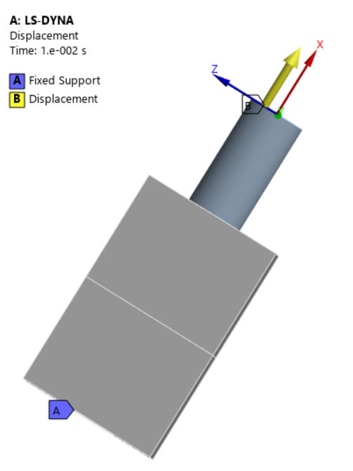
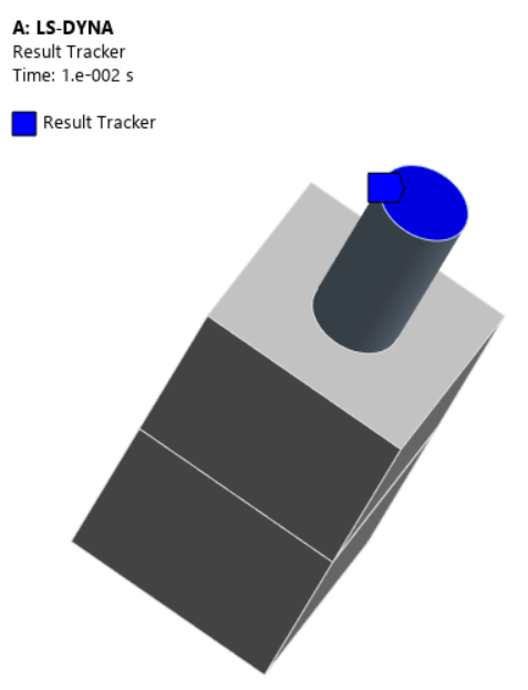
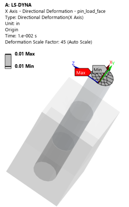
The example model we use is a steel pin bonded into a steel block, rotated by 30° about the global Y-axis, fixed at the base, and subjected to a prescribed displacement of 0.01 in the normal direction to the pin face.
Boundary Conditions and User-Defined Coordinate System
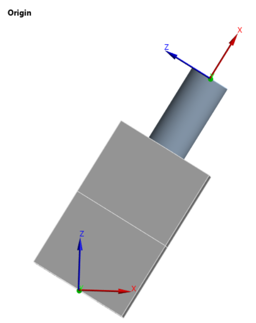
The following images show the orientation and boundary conditions:
 |
 |
The coordinate system named `Origin` is that about which the displacement is oriented and about which the reaction force will be transformed.
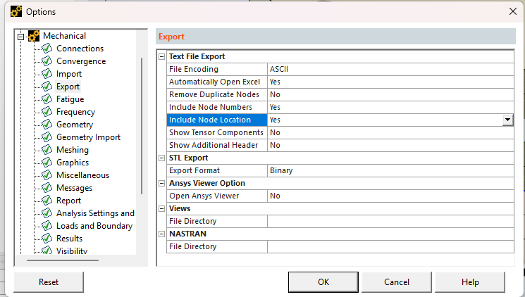
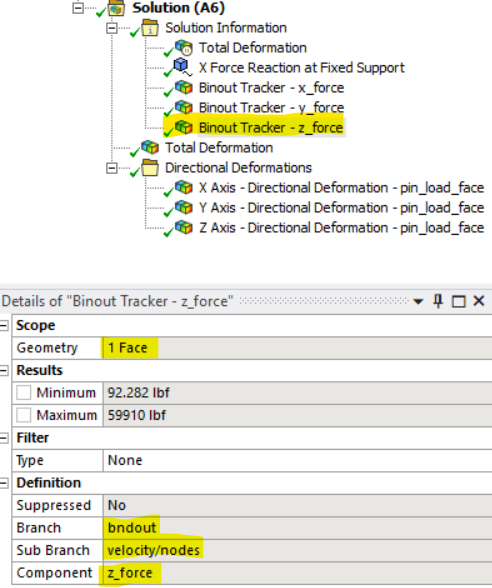
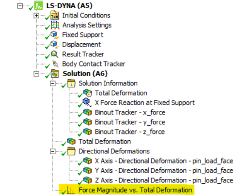
Configuring Result Trackers, Binout Trackers, and Time History Output
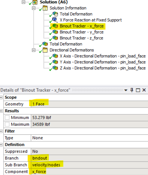
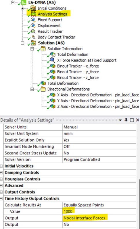
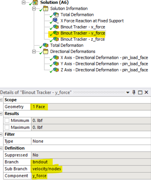
To obtain the reaction force for the applied displacement, WB LS-DYNA requires a Result Tracker and three Binout Trackers scoped to the faces(s) to which the displacement is applied, along with output of Nodal Interface Forces. Each Binout Tracker outputs a force component in a specific global coordinate direction, so it requires scripting to transform the components into the desired output coordinate system. The following images show the definition of the Trackers and Time History Output Controls that output Nodal Interface Forces:
 |
 |
 |
 |
 |
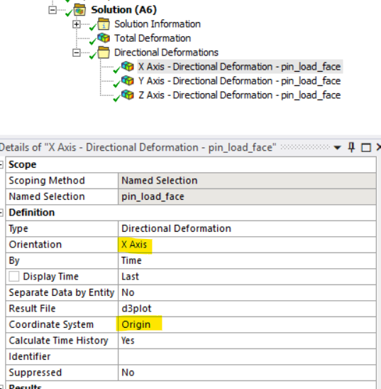
Setting Up Directional Deformation Results Objects
The final required objects are three Directional Deformation Results Objects, scoped to the same faces as the applied displacement/velocity, oriented with respect to the user-defined coordinate system, and grouped into a folder called `Directional Deformations` that distinguishes them from other Directional Deformation Results Objects, scoped to other geometry. The following images illustrate the definition of the one in the X direction; the other two are similarly defined:
 |
 |
Python Script for Reaction Force Post-Processing
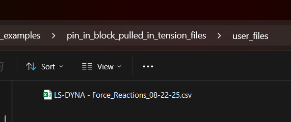
After the simulation is complete, the following Mechanical Script will be used to postprocess the reaction force, outputting its components to a .csv file in the project’s `user_files` directory, and creating a plot for reaction force magnitude versus total deformation.
Pseudocode
The basic algorithm is as follows:
- Get the direction vectors of the user-defined coordinate system and create a transformation matrix.
- For the analysis, get the current model units and desired units for the spreadsheet output.
- Record the data from the Directional Deformation Results Trackers, checking that the correct coordinate system is chosen and adjusting if necessary.
- Compute the total deformation.
- Read each Binout Tracker and store its results in a dictionary. If a Binout Tracker is filtered, use the filtered values and linearly interpolate to align the output times with the Directional Deformations.
- Create Vector3D objects to store the force components and transform them to the user-defined coordinate system directions.
- Place reaction forces in both global coordinates and transformed coordinates, time, and directional deformation components in a dictionary and write to a .csv file.
- Create a line chart of force magnitude versus total deformation.
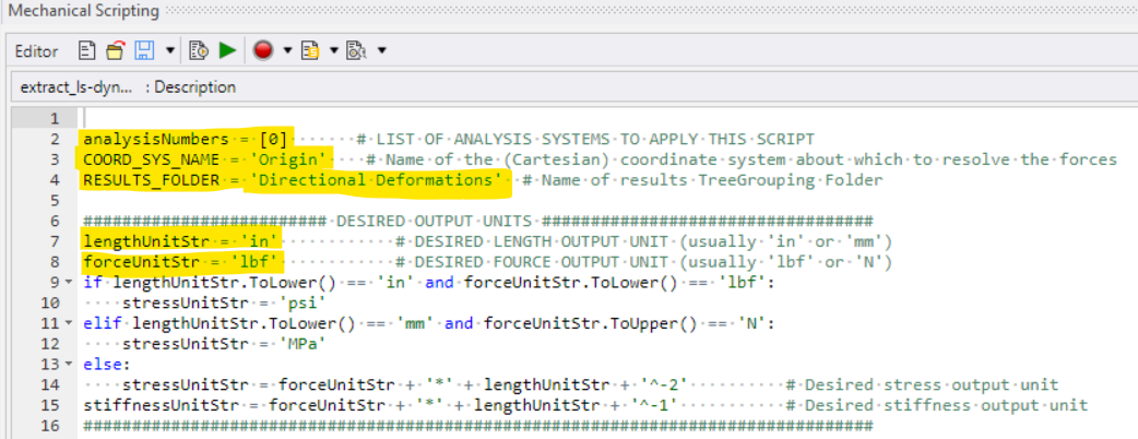
User Configuration
At the top of the script, the user must specify several items: analysis number, user-defined coordinate system name, directional deformations results folder name, and desired output length and force units:
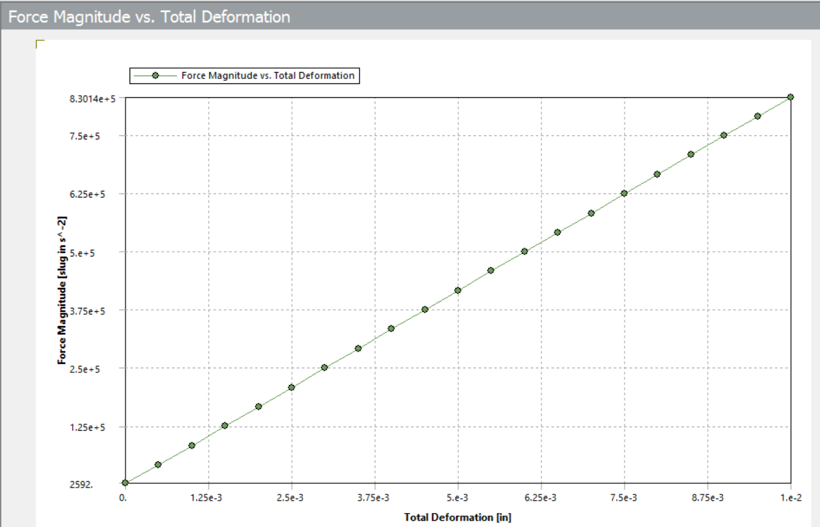
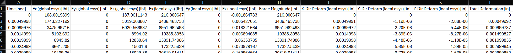
Script Output and Results
Once the script is completed, the Force Magnitude vs. Total Deformation Line Chart is created, and the spreadsheet output is stored in the project’s `user_files` directory. The following images show the Line Chart and a snippet of the output spreadsheet. Note: At the time of this writing, when using Bin units, the force units in the Line Chart are not in lbf, but in slug-in/s^2.
 |
 |
Key Takeaways for Reaction Force Transformation in LS-DYNA
Binout Tracker force reaction results in WB LS-DYNA are only output in global coordinate directions. Therefore, to transform them into user-defined directions or even to compute their magnitude requires Python scripting within Ansys Mechanical. However, as the example in this article shows, it is straightforward to run the downloadable code as a Mechanical script to obtain the desired results.
Going Further
Extend the script to create Binout Trackers, Directional Deformations, and obtain results for any number of desired force reactions in the same model.
Need help with LS-DYNA scripting or reaction force post-processing? SimuTech Group’s FEA consulting engineers work with Ansys Mechanical, LS-DYNA, and Workbench scripting workflows. For more on simulation scripting, see our guide on using Python in Ansys Mechanical to search the model tree and generate scripts. Learn more about Ansys LS-DYNA or contact us to discuss your project.