Why Permanent Magnets Complicate Wireless Charging Simulation
As wireless power transfer (WPT) systems evolve in sophistication and ubiquity—from smartphones to electric vehicles—precision in modeling magnetic interactions becomes more critical than ever. One area gaining traction is the integration of permanent magnets to improve coil alignment and efficiency. However, their nonlinear impact on ferrite materials presents simulation challenges. This blog explores a practical workflow using Ansys Maxwell.
Permanent magnets provide a passive method to stabilize receiver coil positioning. This boosts performance consistency and minimizes misalignment losses. Yet these benefits come with trade-offs: the permanent magnets can saturate the ferrite on the back of the coils, thereby reducing the efficiency of wireless charging.
How Ferrite Permeability Changes Under DC Magnetic Fields
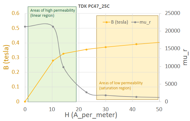
Ferrite material TDK_PC47 is commonly used in WPT devices. The relative permeability of the material is not constant (as shown below) and, depending on its operating point, can range from 1 to 20000. The use of a permanent magnet will introduce a constant magnetic field (H) within the ferrite, which will shift the operating point of the ferrite.
This blog outlines two distinct simulation workflows using Ansys Maxwell.
Approach #1: Linked Magnetostatic and Eddy Current Solvers
This approach requires two models to be created and linked: one magnetostatic model to solve the DC fields from permanent magnets and another eddy-current model to solve the AC fields from the coils.
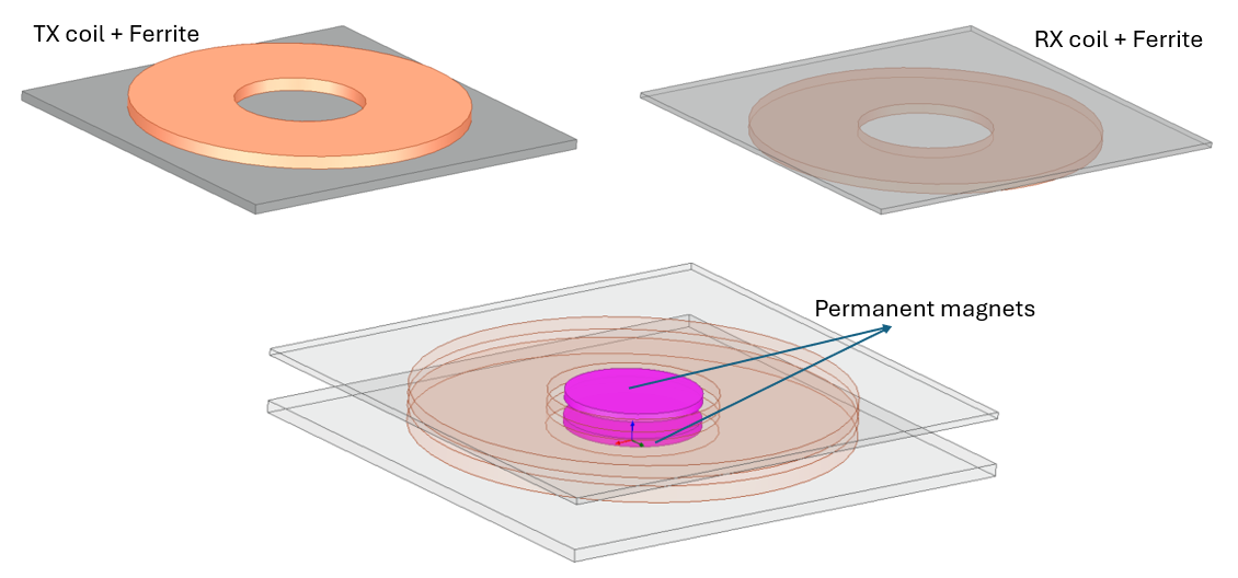
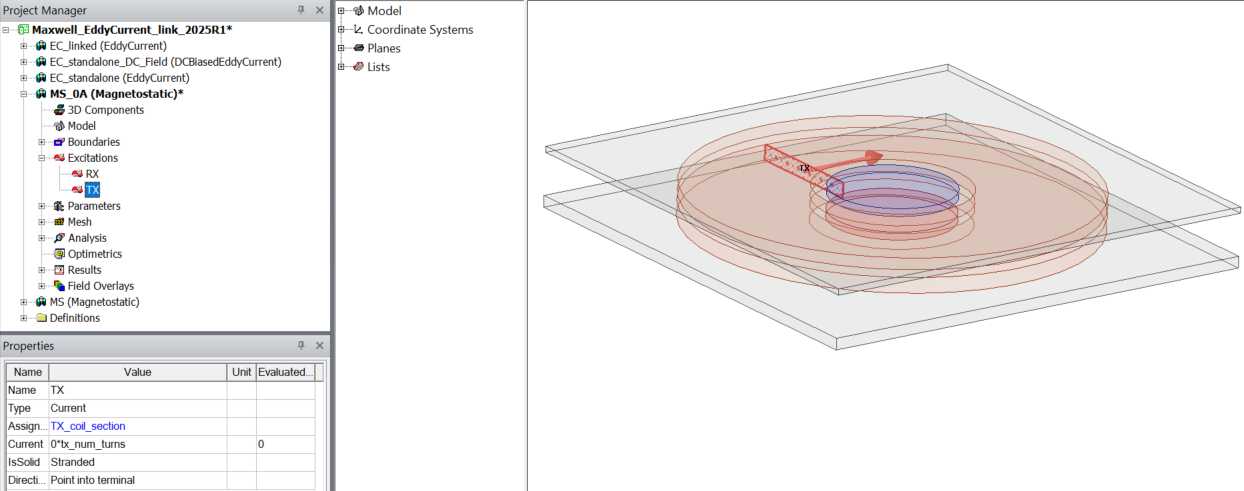
Step 1: The complete model is created in ANSYS Maxwell. It includes the TX coil/ferrite, the RX coil/ferrite, and the TX/RX magnets.
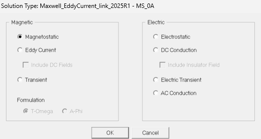
Step 2: Select the Magnetostatic solver to solve the DC magnetic fields from permanent magnets. Make sure the current in the Excitation is zero, as we are only modeling the magnets.
Step 3: Create another model that will use the eddy current solver. This can be done by copying and pasting the Magnetostatic model.
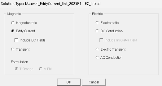
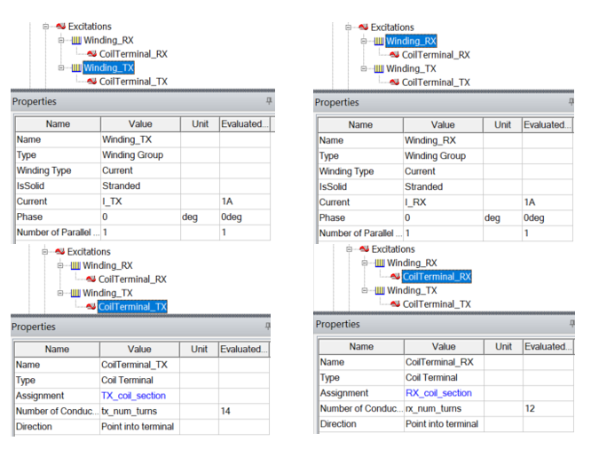
The solver needs to be changed to Eddy Current. Since the AC field from the coil will be modeled, the windings need to be modified (assign # of conductors and current).
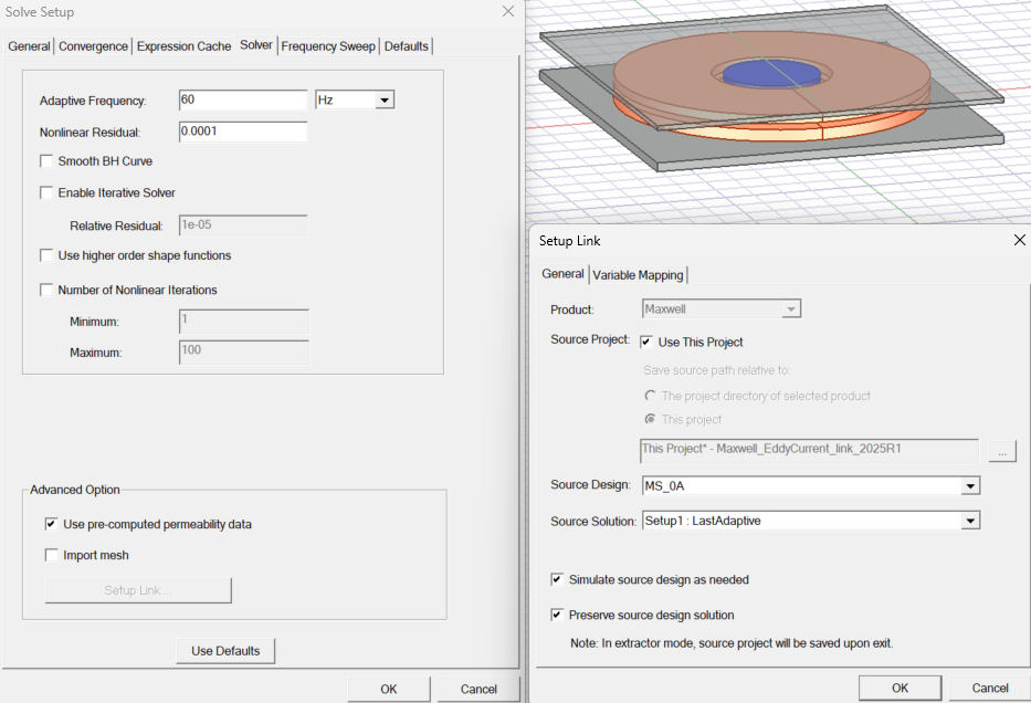
Step 4: Link the two models together and solve the model.
This can be done by adding a solution setup in the Eddy Current model.
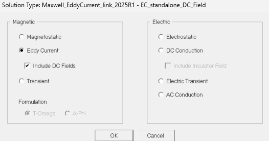
Approach #2: Eddy Current Solver with Include DC Fields (2025 R1+)
This option is available starting from version 2025 R1. With “Include DC Fields” enabled, users no longer need to create two separate models and link them together.
Now, both the DC and AC fields can be modeled with a single model, simplifying the modeling process.
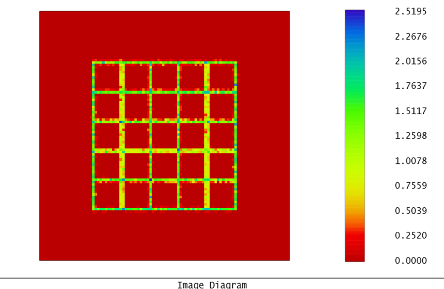
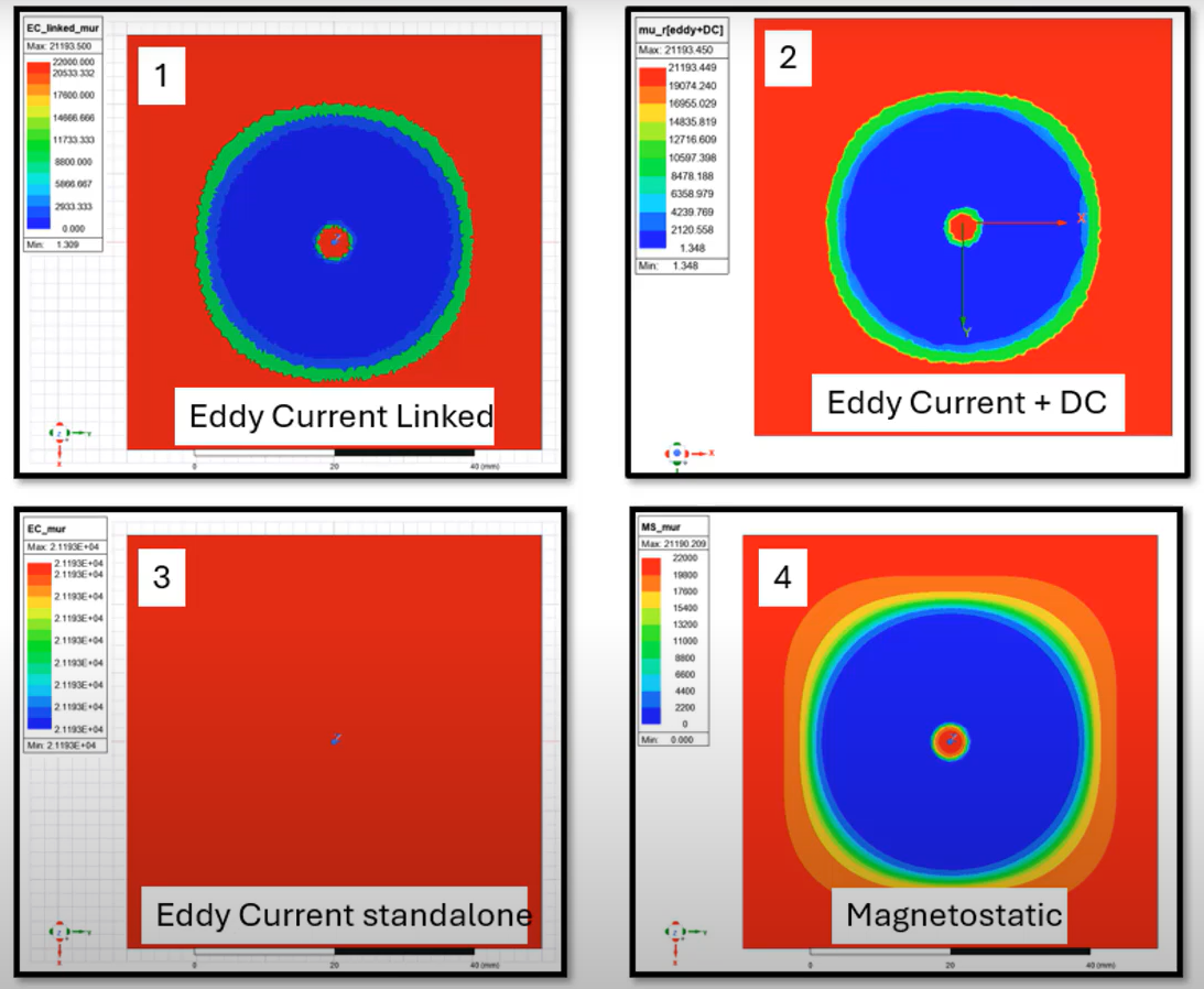
The modeled relative permeabilities from 4 different approaches are compared below.
Comparing All Four Modeling Approaches
The results from #1 and #2 are very close, and both results are correct. The results from #3 and #4 are not accurate enough because the models considered only AC or DC fields.
Approach #1: Magnetostatic solver linked with Eddy Current solver
Approach #2: Eddy Current solver only (include DC Fields)
Approach #3: Eddy Current solver standalone (without including DC Fields)
Approach #4: Magnetostatic solver standalone
The video below walks through these steps in detail.
Working on wireless power transfer or permanent magnet modeling? SimuTech Group’s electromagnetics consulting engineers work with Ansys Maxwell across wireless charging, electric machine, and transformer applications. For more on Maxwell’s capabilities, see our post on electric machine design in Ansys. Contact us to discuss your simulation needs.