Zemax mixed mode simulation lets you combine sequential and non-sequential ray tracing in a single model. This is useful when part of your optical system follows a straightforward path (sequential) but includes a component where rays scatter, reflect, or take multiple paths (non-sequential). This beginner’s guide walks through setting up a mixed mode model in OpticStudio, including the Non-Sequential Component surface, exit port placement, and chief ray centering.
Zemax has two main ray-tracing modes: Sequential Mode and Non-Sequential Mode.
- Sequential Mode is ideal for analyzing imaging systems. There are dozens of useful features and operators to design, analyze, and tolerate an imaging system in which light travels through surfaces in a fixed, sequential order.
- Non-Sequential Mode is a 3D CAD environment ideal for illumination, stray-light, and optical systems that require multiple independent sources (e.g., an array). Light can scatter, split, reflect, or transmit to any surface.
The two Modes described above fit a large category of optical systems, but what if the optical system does not neatly fit into one category? That’s where Mixed Mode becomes useful. It allows you to combine the precision of Sequential Mode with the flexibility of Non-Sequential Mode.
In this Blog, a Mixed Mode example demonstrates the basic settings needed to copy this workflow for your own needs, along with a few tricks to help.
1. Mixed Mode Example: Start
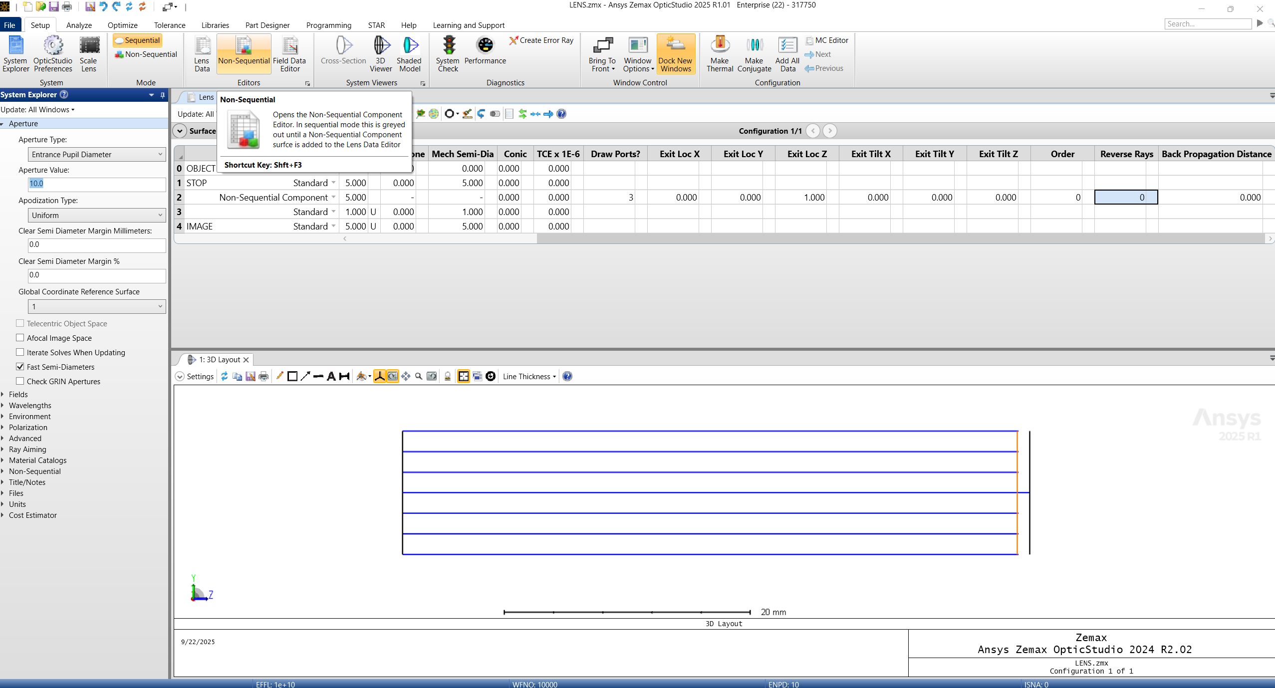
Open a fresh OpticStudio in Sequential Mode. Add your Aperture Settings and initialize your project.
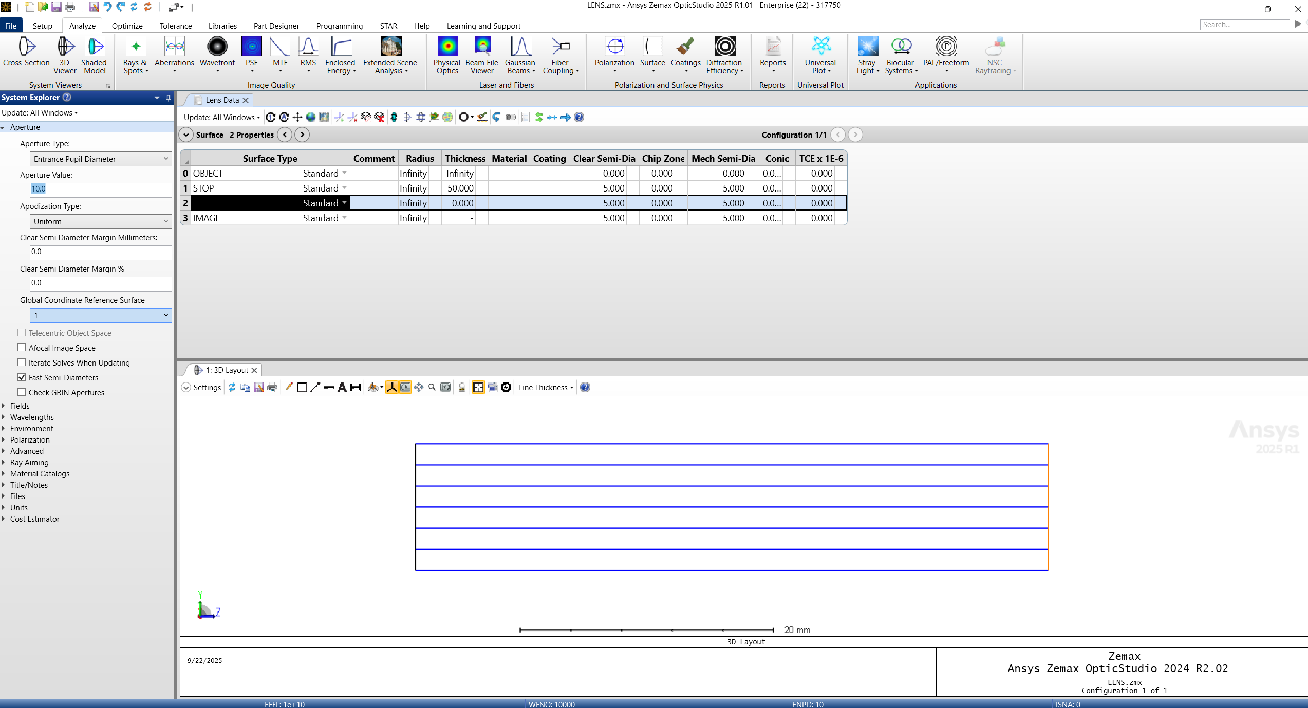
2. Adding a Non-Sequential Component Surface in Zemax Mixed Mode
The Non-Sequential Component Surface is how these two modes interact. The Non-Sequential Component Surface Type must be defined in both the Sequential Mode and the Non-Sequential Mode.
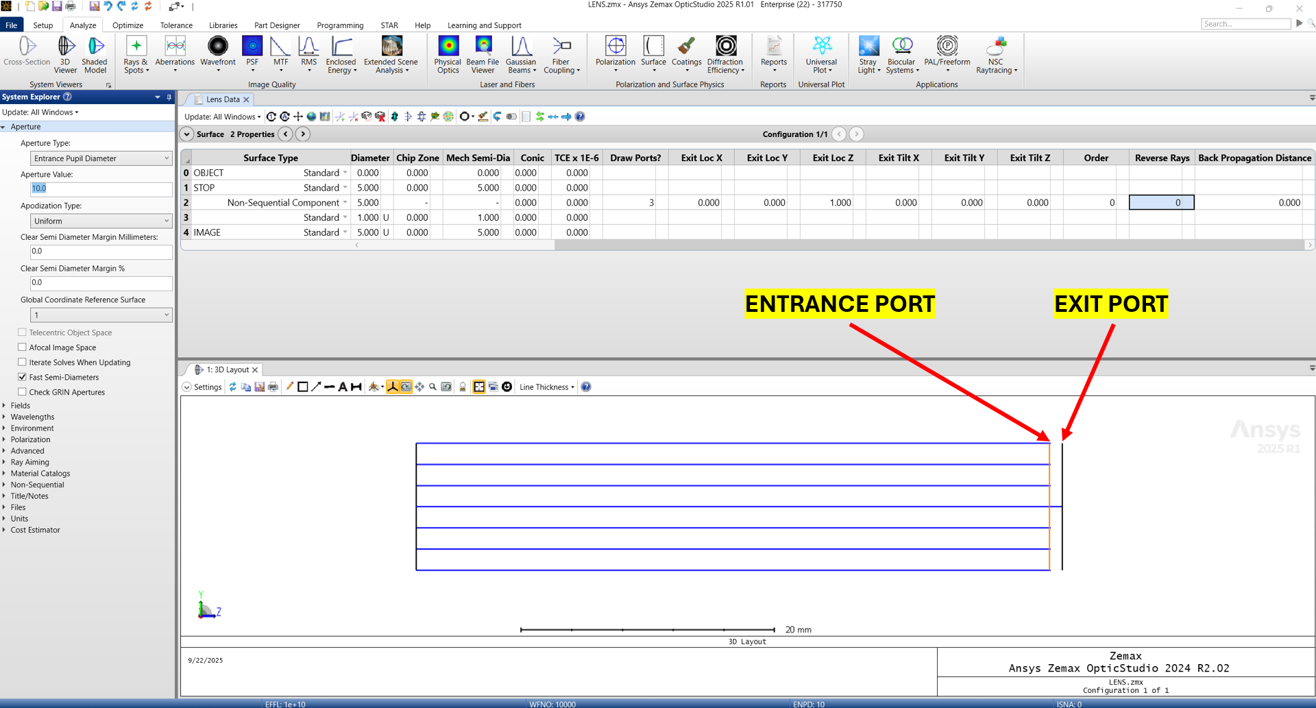
The rays begin in Sequential Mode, then approach the Entrance Port of the Non-Sequential Component. After the Entrance Port, the rays propagate Non-Sequentially and then approach the Exit Port. Once the rays leave the Exit Port, we are back in the Sequential Mode.
The rays will propagate from surface 0 to surface 1 to surface 2. Surface 2’s global location is where the Entrance Port is defined. Parameters 1 through 6 define the global location of the Exit Port.
Sequential Mode Parameters
-
- Parameter 0: Draw ports? 1 draws only the Entrance Port. 2 draws only the Exit Port. 3 draws both.
- Parameter 1: Exit Location on the X-axis with respect to Entrance Port (Surface 2).
- Parameter 2: Exit Location on the Y-axis with respect to Entrance Port (Surface 2).
- Parameter 3: Exit Location on the Z-axis with respect to Entrance Port (Surface 2).
- Parameter 4: Exit Tilt X-axis.
- Parameter 5: Exit Tilt Y-axis.
- Parameter 6: Exit Tilt Z-axis.
- Parameter 7: Order of locations and tilts. (Idea is that a Tilt then Decenter is NOT the same as a Decenter then a Tilt).
- Parameter 8: 0 is refractive, and 1 is reflective.
- Parameter 9: Backpropagate before entering the NSQ Component Surface.
Defining Geometry in Non-Sequential Mode
Define geometry, material, coatings, etc.
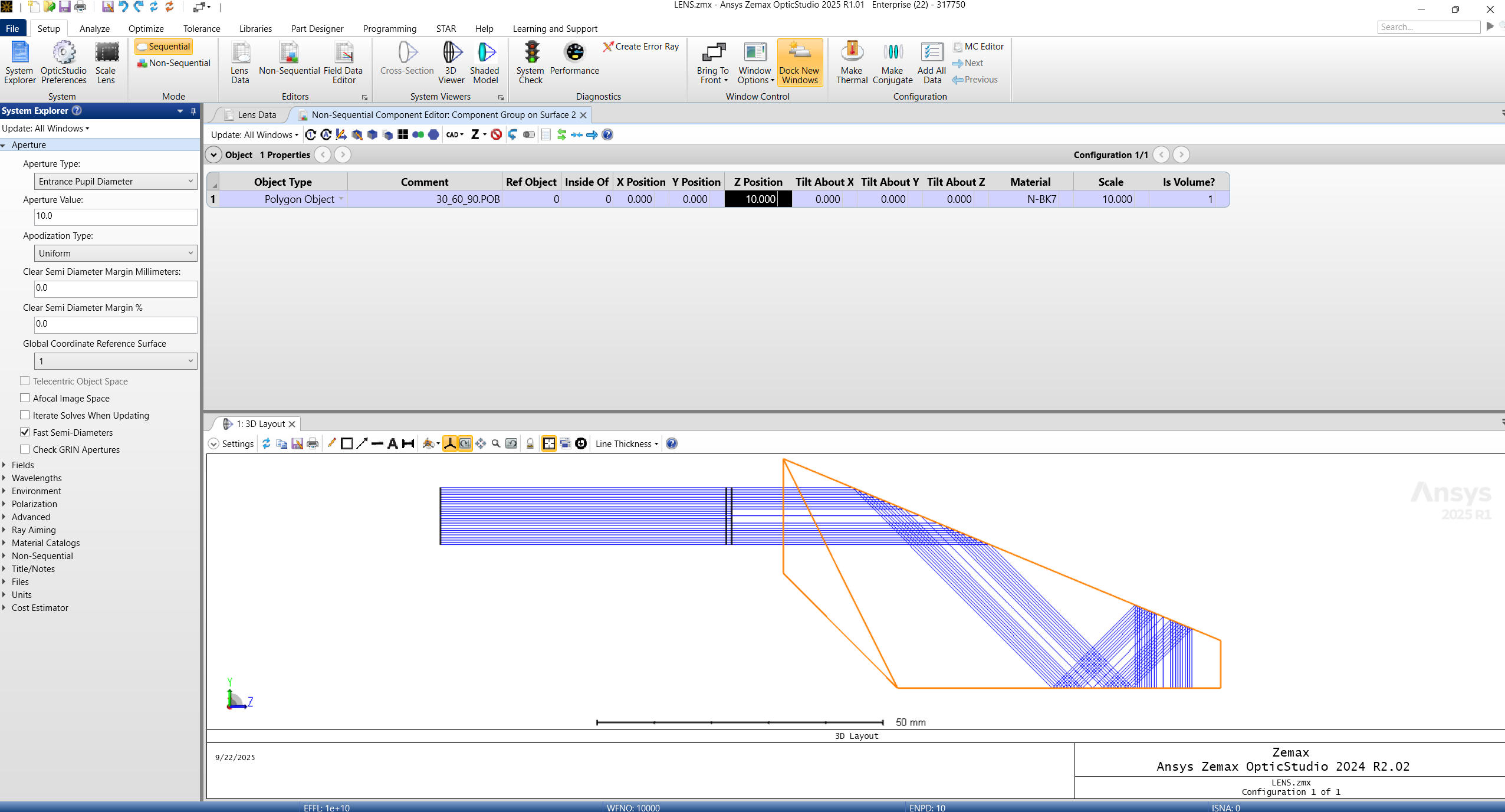
In order to define the geometry of the Non-Sequential Component, click the Non-Sequential Editor by going to Setup > Editors > Non-Sequential.
Once we are in the Non-Sequential Component Editor: Component Group on Surface 2, find an object type and define.
Add your material, coatings, scale, and position the NSQ Object appropriately. Here we are using a pre-defined Polygon Object 30_60_90.POB.
Don’t worry if it looks weird; we have not defined the Exit Port yet (which is defined back in the Sequential Editor).
Placing the Exit Port
Now, place the Exit Port in the correct location. Here we can try and eyeball it, and later we will show how to center the Exit Port on the chief ray.
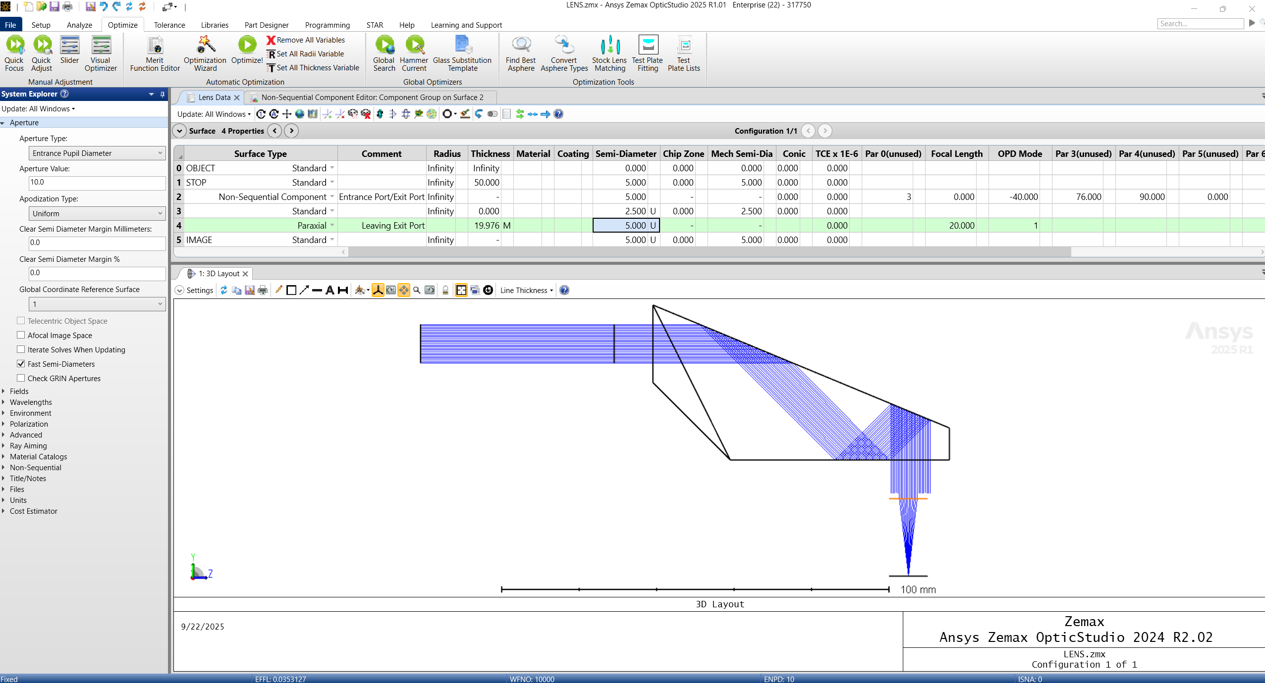
Click the Lens Data Editor.
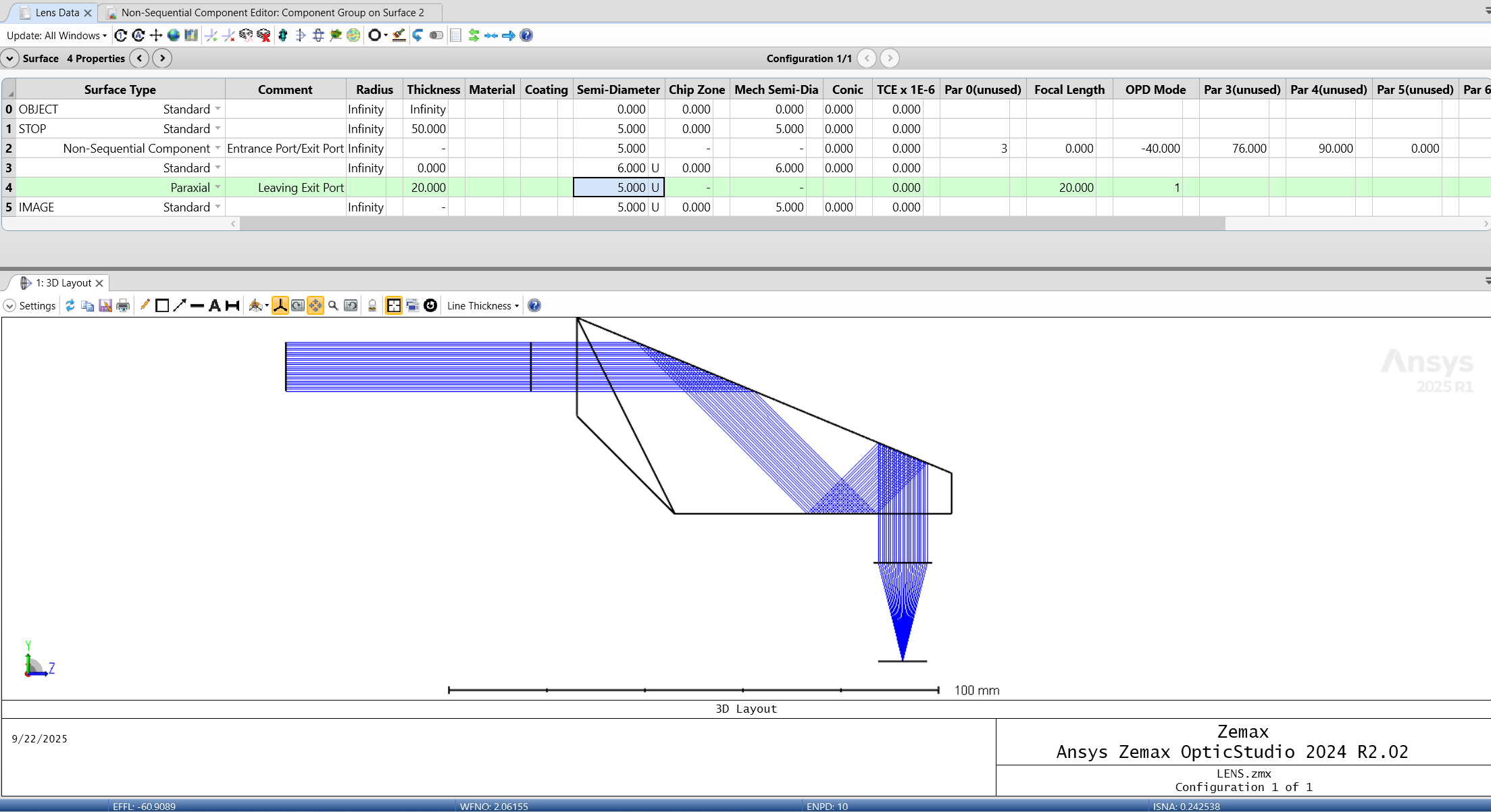
Use Parameters 1-6 on Surface 2 to place your Exit Port. I used 0 for X-Loc, -40 for Y-Loc, and 76 for Z-Loc (relative to Surface 2).
We now have a Mixed Mode Simulation.
3. Centering the Exit Port on the Chief Ray Using the Merit Function
Lastly, we need to place our Exit Port at the center of the beam. I will show a trick that does this with a Merit Function Operand.
Use REAY and REAX:
| REAX | Real ray x-coordinate in lens units at the surface defined by Surf at the wavelength defined by Wave. See “Hx, Hy, Px, and Py”. |
| REAY | Real ray y-coordinate in lens units at the surface defined by Surf at the wavelength defined by Wave. See “Hx, Hy, Px, and Py”. |
All 0’s in the Field and Pupil Coords. will give us the Chief Ray. Not that the Exit Pupil must already be close to the optimal position, otherwise the optimization will diverge to a non-sensical solution.
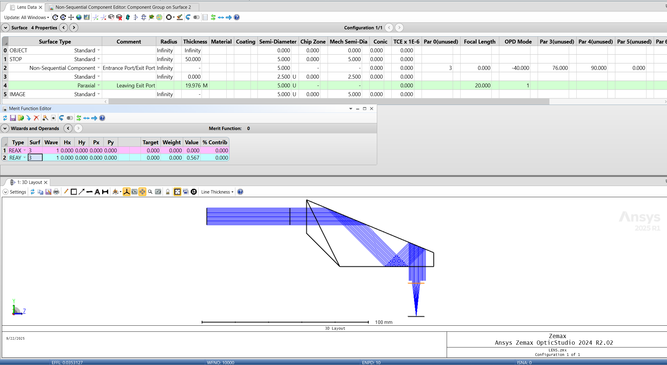
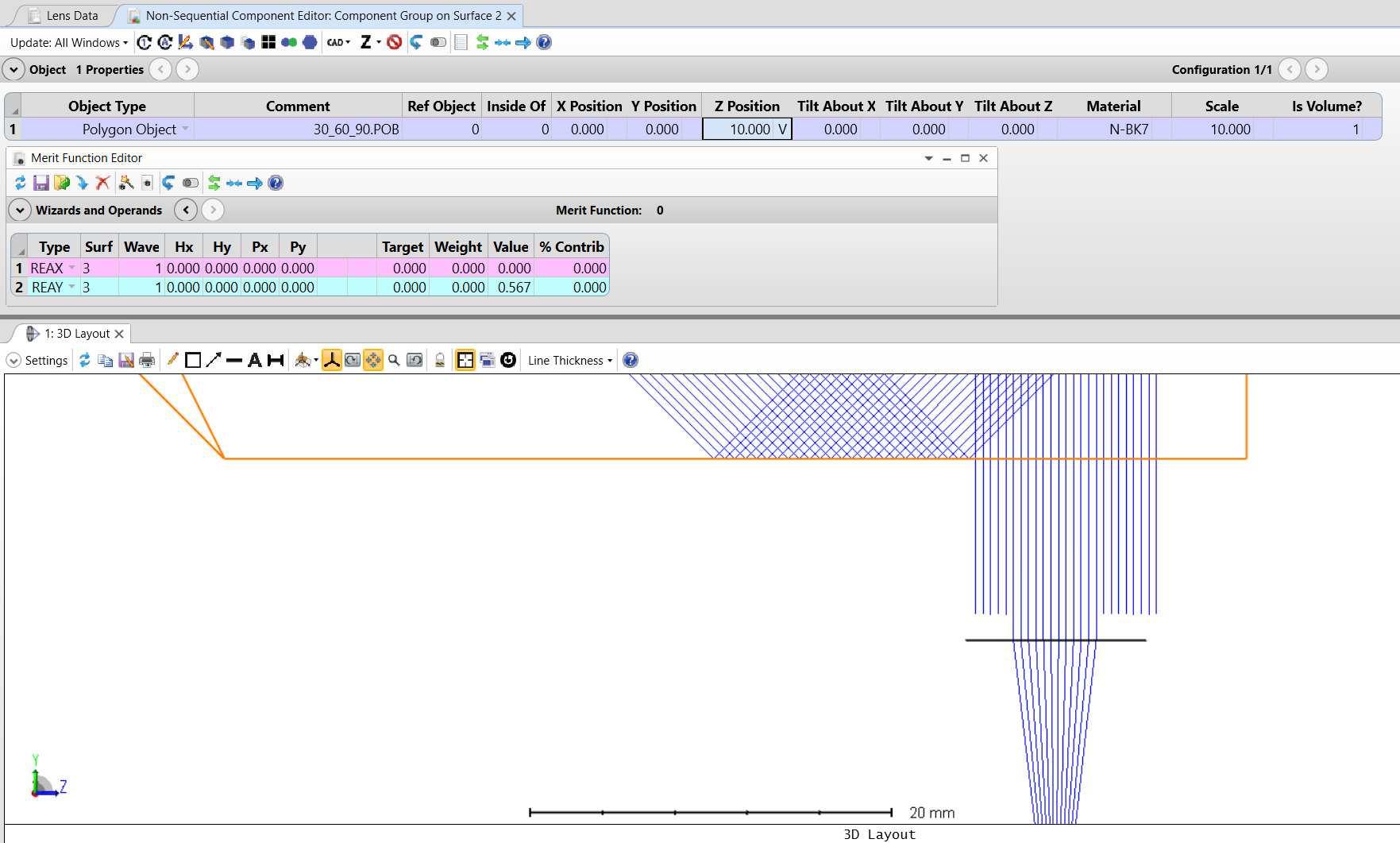
Your Variable will be in the Non-Sequential Component Editor: Component Group Surface 2. We will adjust the position of the NSQ object relative to the Entrance and Exit Ports to determine the optimal position.
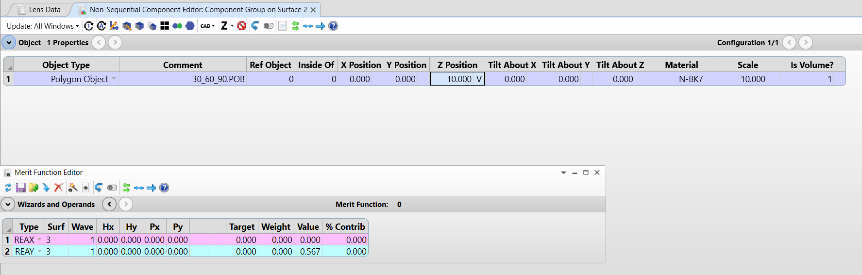
Before Optimization:
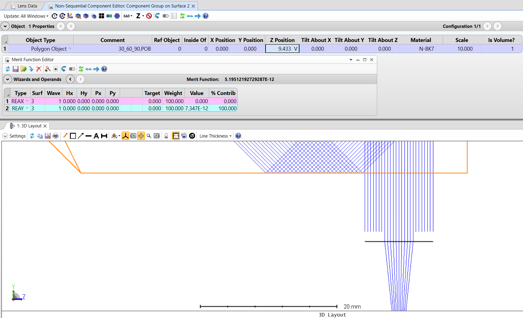
After Optimization: (Click Optimize tab > Optimize!) — Remember to add weights to your operands.
Now we can change the size of the Exit Port using the surface 3 Semi-Diameter to ensure we are not vignetting.
Getting started with Zemax mixed mode or non-sequential modeling? SimuTech Group’s optics and photonics consultants work with Ansys Zemax OpticStudio across sequential, non-sequential, and mixed mode workflows. For more on Zemax surface types, see our beginner’s guide to 5 basic surface types in Zemax OpticStudio. Learn more about Ansys Zemax or contact us to discuss your project.