Induction Heating
SimuTech Group’s induction heating consulting services utilize cutting-edge techniques and the latest simulation software to optimize your electronic and electrical applications.
SimuTech Group’s induction heating consulting services utilize cutting-edge techniques and the latest simulation software to optimize your electronic and electrical applications.
Induction heating is a process that heats electrically conductive bodies as a result of changing magnetic fields. It is typically thought of as the intentional heating of workpieces, but it can also be a result of undesirable heating of conductive components in electrical or electronic applications. Understanding the process can allow engineers and designers to increase heating efficiency, improve heating profiles, utilize induction heating, or reduce undesirable heating.
For more information and details on simulation examples, blogs, ebooks, webinars, or to speak to our induction heating and simulation experts, contacts us today.
The physics of induction heating can be complex due to the multiphysics nature of the applications. But every application begins with electromagnetics. A changing magnetic field ‘induces’ current in nearby conductive bodies. The induced current in the conductive body ‘heats’ it through ohmic heating. Geometry, frequency, and material properties are important for induction heating applications for things like the skin and proximity effects.
Depending on the application, additional complexities may be present, such as nonlinear magnetic properties, temperature dependent material properties, highly transient applications, forces, etc.
In alternating current (AC) applications, the magnetic field does not penetrate conductors uniformly or completely, and the currents do not flow in the entirety of the conductors’ thickness. The current flows mostly near the surface with a drop in the material’s thickness.
It is common to calculate a value commonly known as skin depth, or reference depth, often denoted δ, using the following equation:
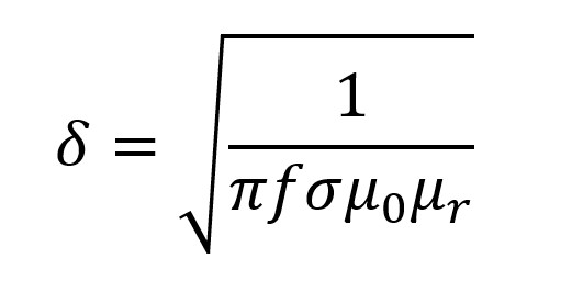
From the previous equation, we can conclude that the skin depth depends on the conductivity, permeability, and frequency. Conductivity and permeability are material properties, and in most cases can’t be changed, leaving frequency as the main variable. (Note: conductivity and permeability are temperature dependent, and permeability is non-linearly dependent on the field.) For electrically large parts at a depth of 1δ, the current density is ~37% of the surface current density and power density is ~13.5% of the surface power density. This means nearly all the power is within 1 skin depth.
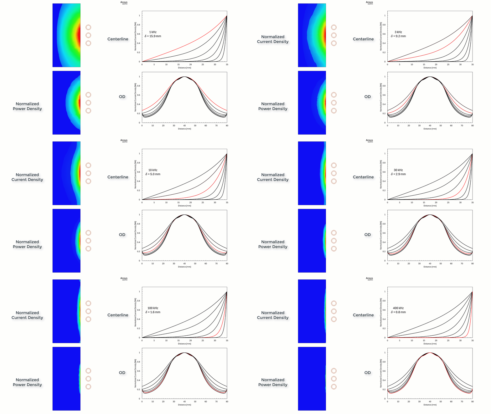
The image shows 2D axi-symmetric simulation of a cylinder. The image shows contours of normalized current and power density and the normalized current density on the center line and OD (end effect) for 1, 3, 10, 30, 100, and 400 kHz frequencies.
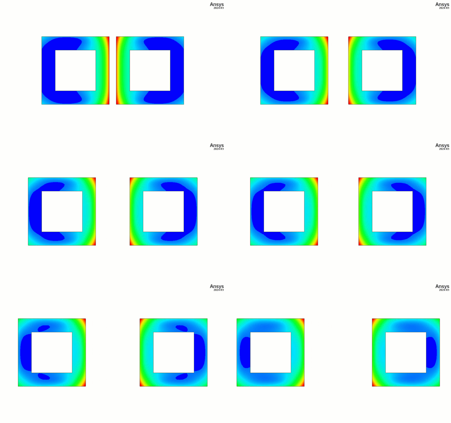
In AC applications, there is a phenomenon known as proximity effect. In simple terms, the current behavior is influenced by magnetic fields (i.e. nearby currents). The example below shows two current carrying conductors at different gaps. We can see the proximity effect is stronger when the conductors are closer to each other. Furthermore, the proximity effect is frequency dependent.
A common saying in the induction heating industry is “it’s easy to design a coil that heats, but it’s hard to design a coil that heats well.” As the industry demands tighter tolerances, more complex heating , more advanced geometries and material properties, it becomes more imperative for the engineers to move away from the experimental methods of development. It is often quite costly and time consuming to utilize iterative experimental methods, as coils, power supplies, samples, and lab times are quite expensive and not always readily available. The alternative is to use computer simulations to predict, iterate, optimize, and investigate the induction heating process before manufacturing coils, procuring power supplies, and running tests.
Ansys simulation tools allow for powerful and versatile simulation of various induction heating applications. Ansys Maxwell is used to solve the Maxwell equations for the magnetic solution.
An Ansys Maxwell simulation can be used to calculate component power losses, magnetic fields, parametric sweeps, inductances, and forces. Further investigation can be done by coupling Maxwell to other Ansys tools such as Mechanical or Fluent.
Ansys software allows for thermal feedback where the thermal solver (Mechanical or Fluent) feeds the temperature back to Maxwell to allow for material properties to update for more accurate simulations.
SimuTech Group engineers have the experience and Ansys tools to simulate magnetic, multiphysics, and optimization for induction heating and other applications.
The example shows the heating of an automotive wheelhub for hardening. The simulation was a transient, two-way, coupled Maxwell-Mechanical simulation. The wheelhub steel had temperature dependent, non-linear B(H) magnetic properties (with Curie point), temperature dependent electrical conductivity, temperature dependent thermal conductivity and specific heat.
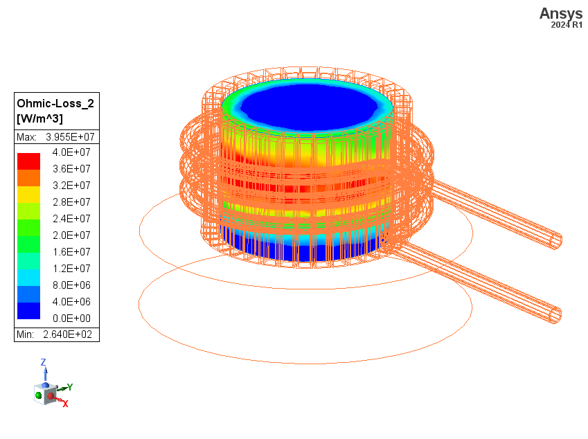
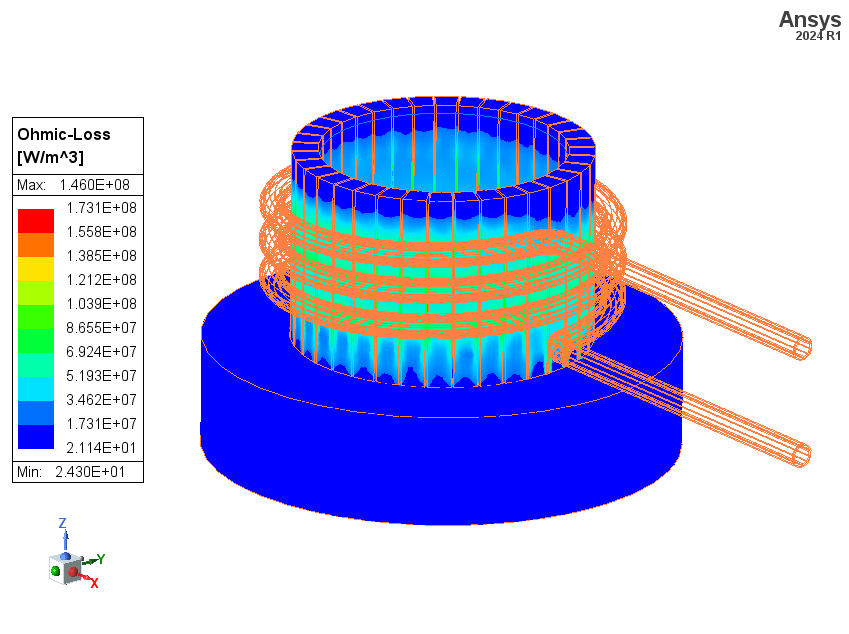
This example shows a 3D simulation of a cold wall crucible induction heating.
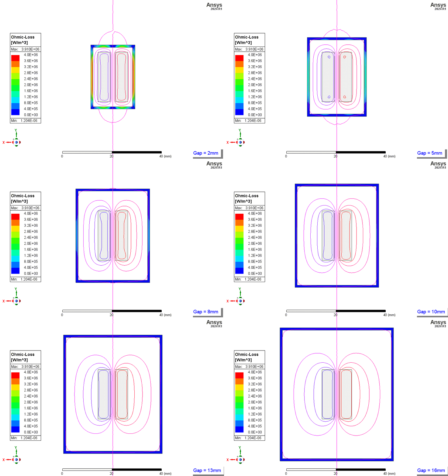
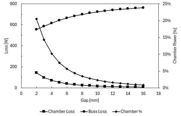
This example shows 2D simulation results of a chamber’s ohmic loss from high current carrying bus bars with varying distance to the chamber walls. The graph shows the losses for 1 meter length of bus and chamber.
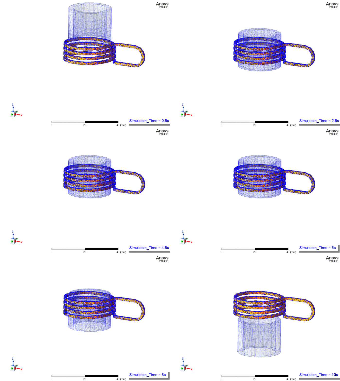
This example shows the heating of a scanning and dwelling tube from a Maxwell-Fluent two-way coupled transient simulation. Workpiece and/or coil translation and rotation is a very common technique in induction heating. Here we should have the ability to do so on a simple tube, but more complex movement paths and geometries are possible.
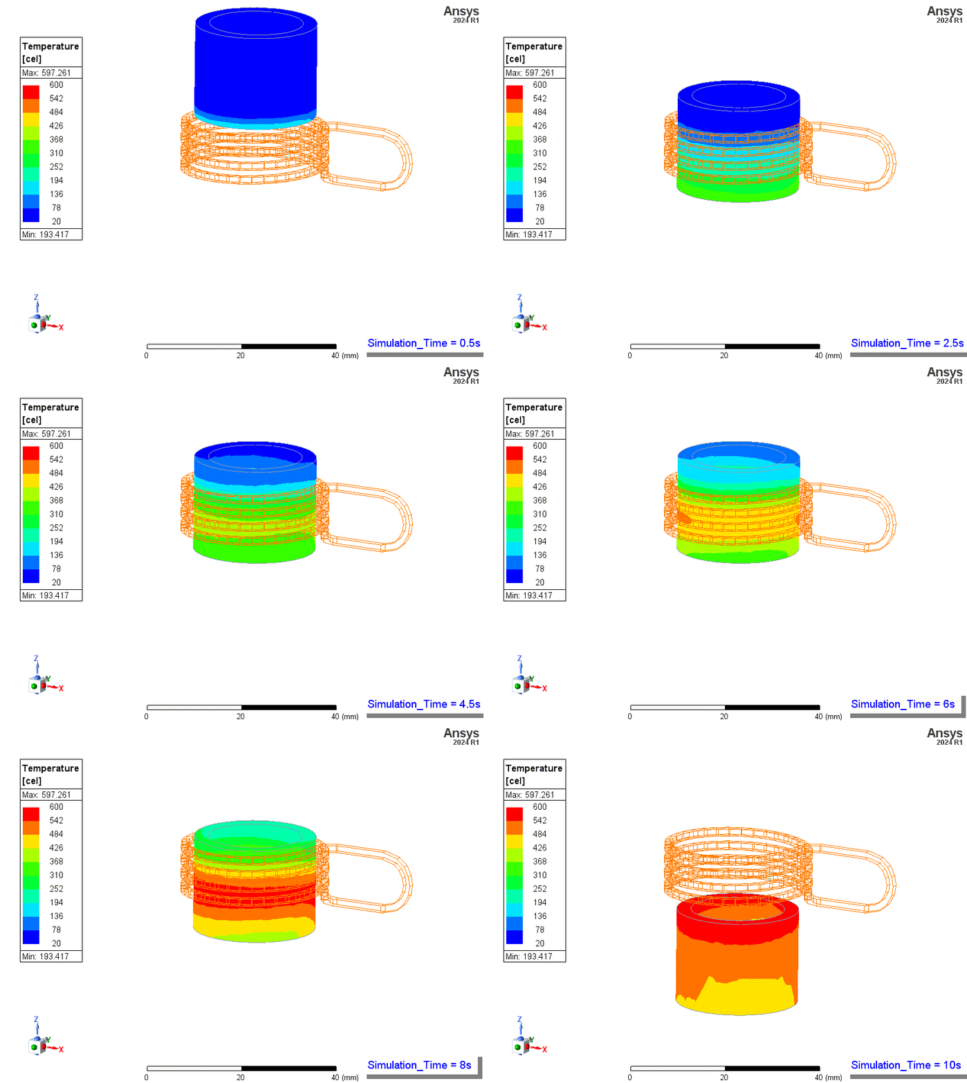
This example shows nut and bolt heating simulation results, a common and popular technique for loosening nuts. Different coil alignments relative to the assembly were tested.
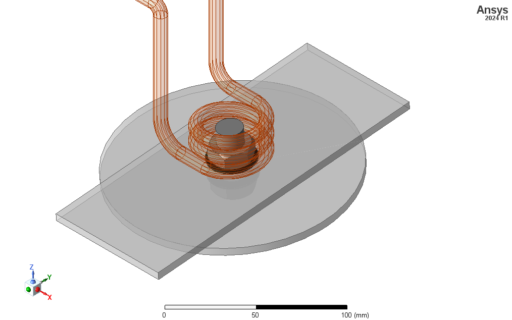
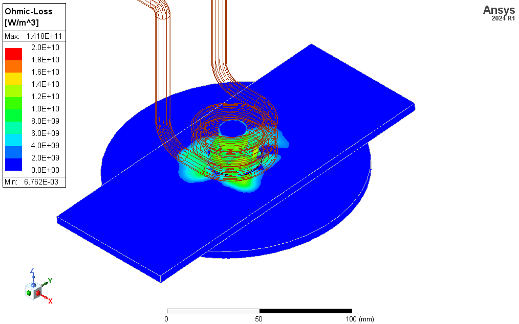
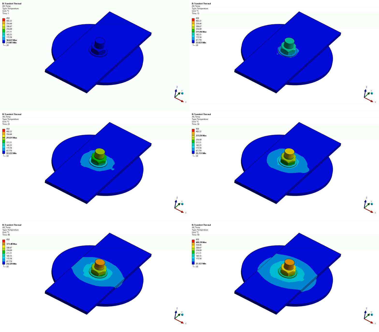
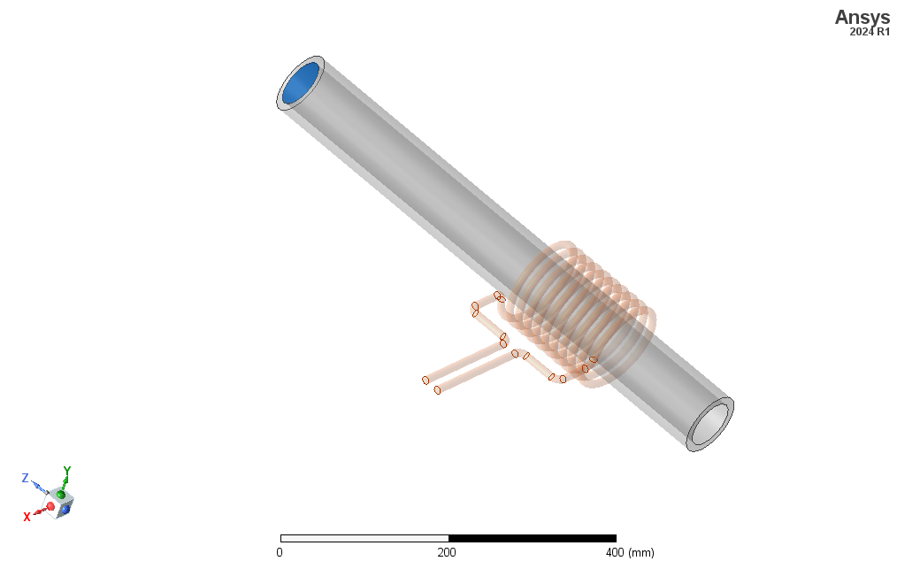
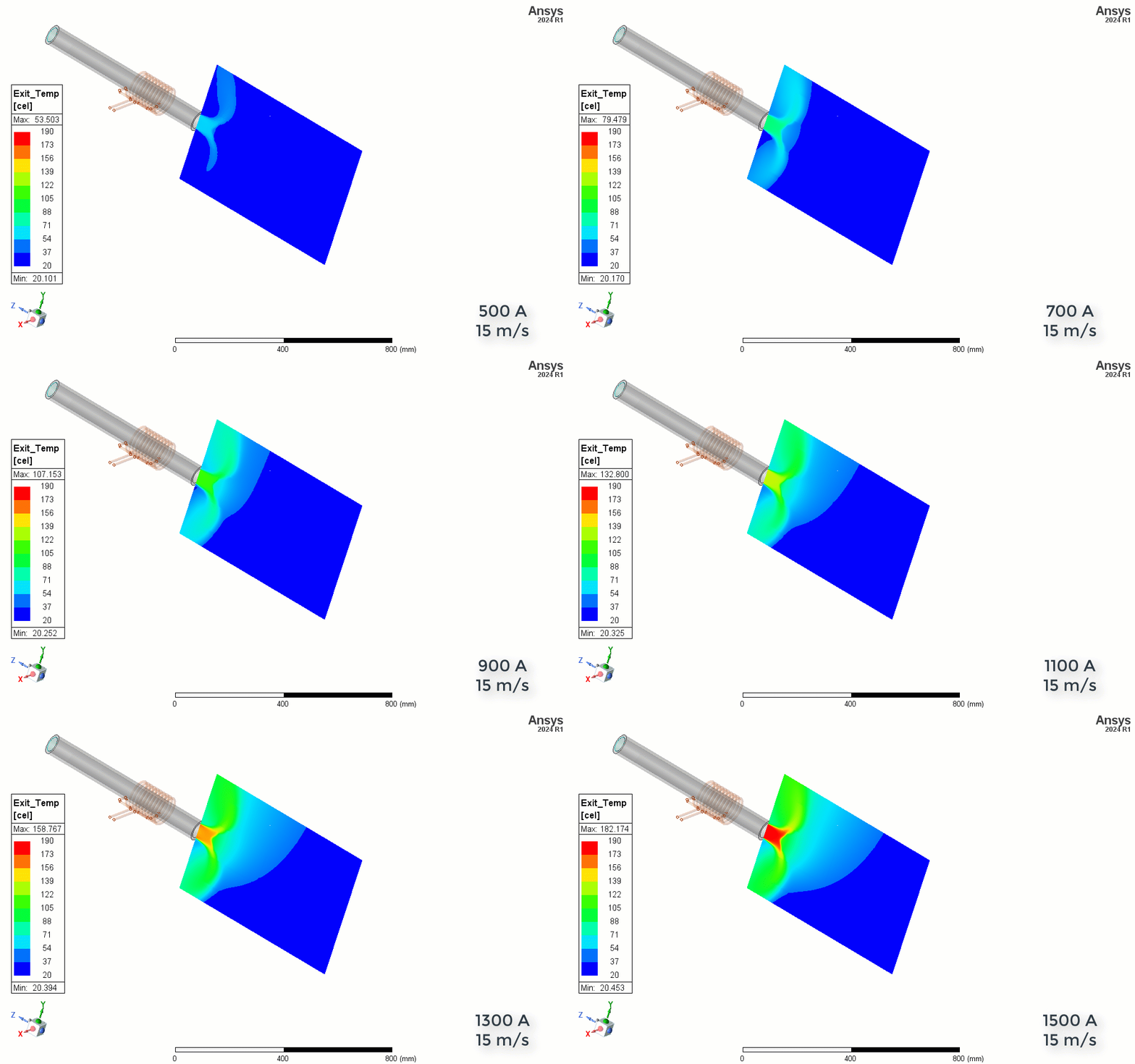
This example shows the heating of air flowing in an induction heated tube, simulated in Maxwell and Icepak.
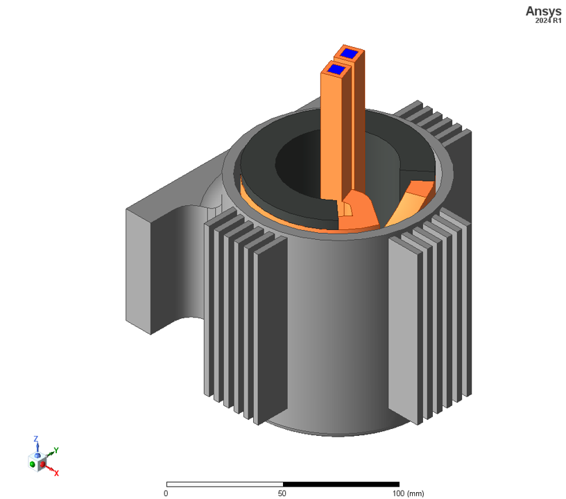
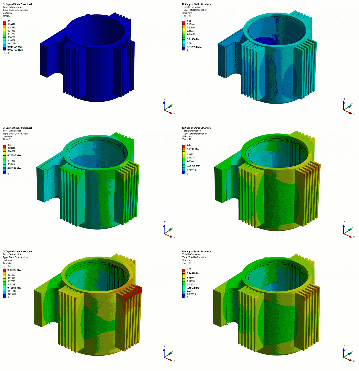
This example shows the deformation of an aluminum motor housing as a result of thermal expansion from induction heating, for the purpose of shrink fit. Note that deformations in the animation are scaled up for visualization.
Our team of experienced engineers can assist you at any step of your process.