The Shrink Fitting Challenge
Shrink fitting a rotor/stator assembly into a housing using induction heating is an exciting and advantageous technology, but it does have some considerations and challenges that simulation can thankfully help to predict, optimize, and improve. We’ll discuss those challenges, as well as how to solve them, after providing some important background on shrink fitting, induction heating, and the physics (and multi-physics) involved in this topic.
What is Shrink Fitting?
It is well known that materials expand when heated. This behavior is known to engineers and can be anywhere from irrelevant to catastrophic if not accounted for appropriately. But, it’s also a behavior that can be utilized and designed for, as in shrink fitting.
In manufacturing, sometimes a component needs to be placed in another component and held firmly. For this, fasteners, adhesives, welding, and other techniques can be used. Shrink fitting is an interference fitting technique where the outer component’s bore is slightly smaller than the inner component’s diameter. It is expanded by heating and the inner component is held in constant compression after cooling.
Why Use Shrink Fitting?
Why use shrink fitting instead of other joining techniques? For applications where uniform contact between the components is needed, local stresses are highly undesirable, fasteners add high imbalances to a rotating component, or large bores make welding impractical, shrink fitting can be a great candidate.
What is Induction Shrink Fitting?
As shrink fitting works by heating, induction heating is a great candidate. Induction heating works by inducing currents in the workpiece to heat it through ohmic heating. This is done by using an inductor, known as a coil, carrying alternating current and generating an alternating magnetic field. The typical geometry of a nice, clean bore is a great application for induction heating.
The coil can be used internally (ID style) or externally (OD style) depending on the application specifics (geometry, materials, etc.).
Why Use Induction Heating?
Induction heating is a great technology for shrink fitting applications and is gaining popularity for its advantages. Here are some of the advantages of induction heating:
- Efficiency: as the heating is done individually for each component, energy is only used during the heat cycle. This contrasts with furnaces that need to be constantly powered on. Furthermore, the heating is directed, meaning energy is used to heat the desired locations only.
- Directed heating: only the location that needs heating is heated. This allows the use of lower temperature materials (such as gaskets) elsewhere on the part or to avoid damaging the product (tempering, soldering, etc.).
- Fast heating: induction heating is known for its rapid heating rates. While shrink fitting applications require time to conduct the heat through the thickness, significant process speedup can still be achieved.
- Individual heating: as the heating is part of a larger manufacturing process, it needs to fit with the rest of the stages, such as the insertion. Induction heating allows for each component to be heated individually, making it integrate well with the rest of the process. Increasing the number of parts simultaneously heated can be easily implemented.
- Controllability, traceability, and feedback: most modern power supplies have control capabilities and integrate well with the rest of the automation stages. This allows for feedback, parameter logging, control, and traceability.
- Other advantages: induction heating is clean; there’s no gas, exhaust, or soot. The induction areas are cooler than furnaces. Induction heating equipment can command a lower footprint in manufacturing plants.
What Are the Challenges with Using Induction Shrink Fitting?
While induction heating can be a great candidate for shrink fitting, there are considerations and challenges with using it and optimizing it. For instance, coils are generally designed specifically for the workpiece. While an off-the-shelf coil or shared designs may be used, those will not be properly optimized.
Furthermore, workpieces tend to be geometrically complex, unlike the examples shown here. Complexity includes non-uniform mass and surface area distribution areas due to cooling fins, cooling channels, and mechanical components. Heat, temperature, and expansion uniformity are not necessarily correlated in complex geometries, and because of this, internal stresses may arise. Moreover, lack of understanding of induction heating can result in improper implementation or bad coil designs or process parameters.
Finally, procurement of equipment and tools can take a long time, as coils are specifically manufactured, and power supplies may take weeks or months to ship and have set specifications and ratings (power, frequency, voltage, current, etc.). Therefore, the user needs to know the process parameters and coil geometry, which affects the process parameters and heating profile, and match them before purchasing (or guess the parameters and geometry and hope they are correct).
Another option could be to manufacture a coil, test it in a lab with a rented power supply, and then order the equipment. This is time-consuming and often not possible, for instance, when the workpiece is still in the design stage.
Motor Housing Induction Shrink Fitting
It is common for electric motors to have the rotor/stator assembly mounted within a housing. The housing commonly contains cooling fins, cooling channels, electrical components, and mechanical components.
One of the biggest markets for motor housing induction shrink fitting is the automotive EV market.
How Does Simulation Help with Induction Shrink Fitting?
As mentioned earlier, there are challenges with implementing induction heating for shrink fitting. Simulation can help in the following ways:
- Heating profiles: simulation allows engineers to predict temperature profiles without having tools or equipment.
- Unknown parameters: one of the challenges of these applications is not knowing the process parameters. Simulation solves this problem by allowing the engineers to predict and calculate the necessary values before purchasing. It also has the advantage of preventing the purchase of oversized equipment.
- Process design and optimization: for an optimized process each application needs its own coil and set of parameters. Engineers can simulate the process with different coil designs and parameters and can run sensitivity analyses to better understand the process. Simulation also allows for faster testing and changes than experimentation. For example, design changes or frequency changes are much easier to run than manufacturing additional coils or changing equipment.
- Predicting expansion and stresses: often engineers know the desired expansion for the shrink fitting but not the required temperature, or may just have material temperature limits. Simulation gives insight into these unknowns and correlates them. For example, simulation can predict the expansion from heating within the limits, or what is the minimum temperature to achieve the desired expansion, and their respective stresses.
- Process insight: in practice, the shrink fitting stage happens after the induction heating by some time. This results in a temperature drop and some equalization while the housing is moving to the shrink fitting stage. This also results in the housing contracting slightly after peak temperature. The transfer time becomes a crucial process parameter. As it gets longer, the temperature drops, so higher maximum temperature will be needed. Decreasing the process time is challenging from an automation standpoint. Simulation allows the prediction of the temperature and expansion after the heating stage, giving the engineers insight for the automation process.
- Feasibility: sometimes a technology seems viable at first but needs to be explored to determine feasibility. Simulation allows the prediction of the process parameters and results without purchasing tools, equipment, and/or investing in lab time.
How Can Ansys Simulation Software Help with Induction Shrink Fitting?
Ansys has an entire suite of simulation tools spanning various physics and technologies. As induction shrink fitting is a multi-physics application, multiple simulation tools can be used. Ansys has many industry-leading simulation tools for every physics needed to simulate induction shrink fitting.
Ansys Maxwell, an advanced electromagnetic field solver, simulates the electromagnetics. From it we can get the current, voltage, power, frequency, and heat distribution. Ansys Mechanical, which is Ansys’ premier structural and thermal FEA analysis software, takes the heat data from Maxwell to simulate the heating, calculating temperature distribution vs time. Then the temperature can be used to calculate deformation (expansion) and stresses.
Ansys Workbench is a program designed for coupling Ansys simulation and geometry tools. It allows for easy transfer of geometries and loads, in addition to running multiple ‘design points’ for different simulations with parameters.
Additional tools may be used if needed, such as Ansys Fluent fluid simulation software for the coil heating and cooling (coils are generally water-cooled) or Ansys System Coupling for transient two-way coupled simulations.
How Can SimuTech Group Help You with Simulating Induction Shrink Fitting?
While simulation is great for developing and optimizing induction shrink fitting and other applications, it requires expertise in its tools and technology. SimuTech Group is an Ansys Apex Channel partner, staffing many highly experienced engineers who are experts in different physics, tools, and industrial experiences, including induction heating. It is common for the end user to be highly experienced in automation, motors, or EV applications, but not in simulation or induction heating. SimuTech Group engineers can help with simulation, turn results faster, and allow the end user to focus on what they do best.
Generally, simulations need to simplify real-world applications. Which simplifications are acceptable and what their effects include is an application specific determination. In practice, these choices range from insignificant to very costly.
For example, should the simulation have temperature feedback or a constant temperature? Should the feedback be every time step, and if so, what is an acceptable time step? One choice is a simple one-way coupled simulation, while the other is a transient two-way coupled simulation. The two-way coupled simulation is more representative of the real-world application. While it is possible to do, it takes a significantly longer time to solve for a marginal increase in accuracy, which is compounded if numerous revisions and simulations are made.
These questions can be posed for the geometry, mesh, boundary conditions, material properties, solvers, coupling, parameters, physics, and more. An inexperienced engineer may make mistakes or solve an unnecessarily complicated version of the simulation. SimuTech Group engineers can help the end user by leveraging their experience to deliver the best possible simulation for the project’s needs and limitations.
If a user does not have experienced simulation engineers, does not have the capacity, does not want to take simulation in-house, would like to purchase the tools but needs help with the simulation, or has the tools but needs help to learn how to use them for induction shrink fitting, SimuTech Group engineers can help.
What Does Induction Shrink Fitting Simulation Look Like?
Here’s an example of an induction shrink fitting simulation done using Ansys simulation tools. This example shows a simple, generic housing and an ID coil with magnetic concentrator.
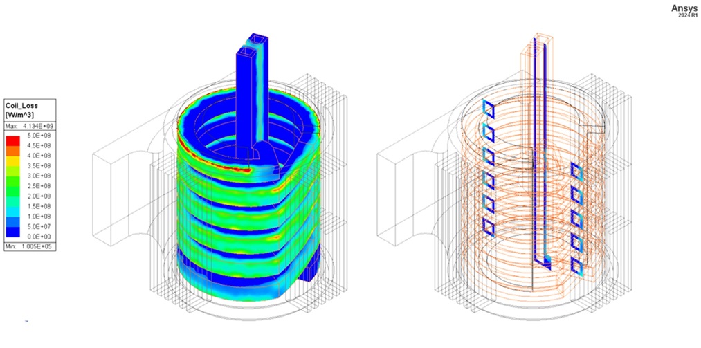
The image above shows the coil’s ohmic losses. The losses are used for a transient simulation in Ansys Mechanical. If needed, a CFD simulation can be made using Ansys Fluent to predict the temperature and flow. Elevated temperatures, global or localized, can result in faster copper degradation and a decreased coil life. While this type of application tends to have lower coil temperatures, it may still be worth verifying with simulation.
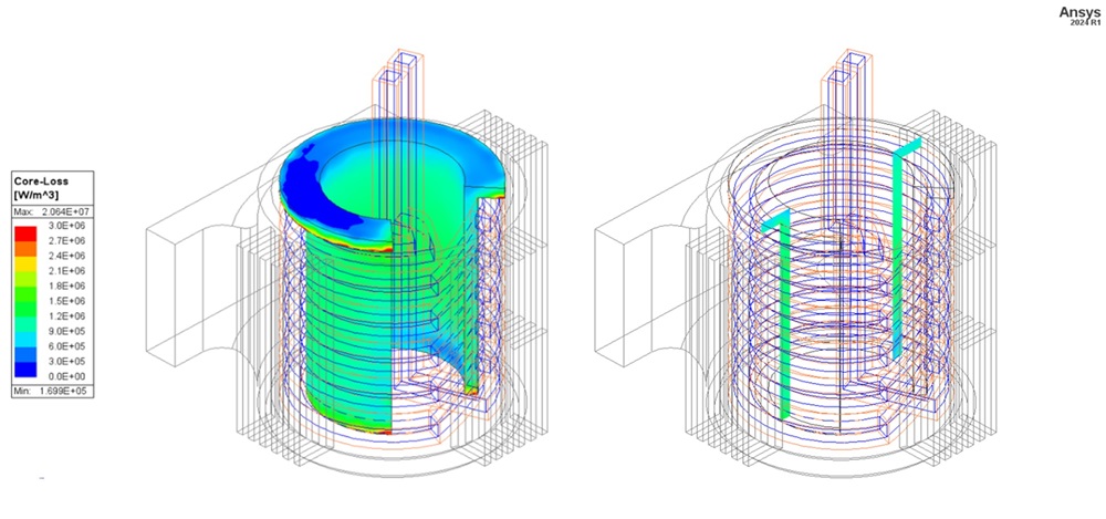
The image above shows the concentrator’s core loss. The losses are used along with the coil’s ohmic losses to predict the coil temperature. Concentrator temperature is important because they are often made from composite materials and if the temperature exceeds the limit, even locally, it can cause irreversible damage to the binder material, dropping the local resistance and increasing the heating, which results in a runaway effect. While this is generally not seen in shrink fitting applications, it is common in other induction applications and may be worth investigating.
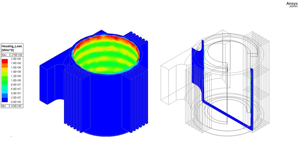
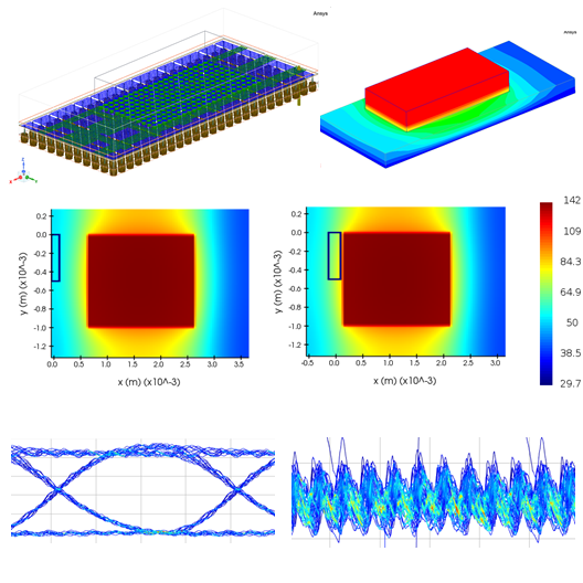
The image above shows the ohmic loss contour in the aluminum housing. These losses are solved in Maxwell and transferred to Mechanical for thermal and structural simulations.

The image above shows the housing temperature during the heat and cooldown. The simulation was done in Ansys Mechanical using the heat from Ansys Maxwell. The temperature contours are shown from two views. The graph shows the temperature minimum, average, and maximum vs time.
The image above shows the temperature on the bore face only.
The image above shows the housing’s total deformation (expansion) at 50x scale during the heat and cooldown. The simulation was done in Ansys Mechanical using the temperature from the thermal simulation.
The image above shows the radial deformation relative to the center of the bore at 50x scale during the heat and cooldown. The graph shows the minimum, average, and maximum radial deformation vs time. Radial deformation of the bore is usually the result of interest, as it signifies the clearance for the component to be inserted.
The image above shows the stress in the housing vs time. The results are from the static structural simulation. Stress is important to monitor to ensure damage or plastic deformation does not occur during the heating cycle.
The image above shows the coil temperature vs time. The ohmic loss and core loss from Maxwell were used. The results show quick equalization, which is expected due to the high conductivity. The maximum temperature of ~43°C is a low and safe temperature, indicating a safe operating temperature. More aggressive heat cycles or multi-step heating recipes will increase the coil heat and temperatures.
Conclusion: What to do Next?
Induction shrink fitting is an exciting technology. It has the potential to streamline manufacturing processes for many industries. It has many advantages, including higher efficiency, lower footprint, clean operation, better traceability, and improved process operation. The technology has a multi-physics nature, lending itself well to simulation, and can benefit well from Ansys simulation tools and optimization.
If you are looking to investigate the benefits of using simulation for your induction shrink fitting project, or for any of your induction heating needs, SimuTech Group’s team of experts is here to help. With extensive simulation consulting experience and access to Ansys’ most advanced multi-physics simulation tools, we can guide you through the entire process, from initial design requirements to detailed analysis and optimization. Contact us today for a consultation, and discover how multi-physics simulation can transform your design process and elevate the performance of your induction shrink fitting application.
About the Author

Tareq Eddir, B.S.E. Chemical Engineering
Staff Engineer, SimuTech Group
Tareq has worked in the induction heating industry for over eight years with experience in simulating, optimizing, consulting, testing and troubleshooting induction heating applications. His work includes leading a host of interesting projects across various industries, including heat treatment, melting, shrink fitting, and much more. He has been a member of SimuTech Group’s low frequency electrical team since 2022, with interest in low frequency and thermal coupled simulations.
Related Content
Ansys Electronics Suite Software
Design electronic and electrical products more quickly and cost-effectively with Ansys electromagnetic (EM) software solutions.
FEA, Structural Analysis & Thermal Consulting Services
Ensure the structural integrity, performance, and reliability of your designs with our expert FEA consulting services.
Engineering & Simulation Webinars
View upcoming and on-demand webinars while learning about simulation software features, updates and best practices.
Industry Solutions
SimuTech Group provides industry-specific capabilities and expertise that deliver the flexibility and scalability you need for your specific projects.