Contact Us
Introduction
In this blog, I examine the main methods for modeling thin solids in Ansys Icepak, with a particular focus on the Conducting Plate feature.
Icepak provides several options for representing thin objects, as summarized in the table below.
| Plate type | Physical thickness | Heat transfer | Typical use |
|---|---|---|---|
| Conducting Thick | Yes | Conduction, radiation | Solid objects with small thickness |
| Conducting Thin | No | In-plane and through-plane conduction | Thin layers and CAD shapes |
| Contact Resistance | Surface mesh | Through-plane heat transfer | Adhesives and interface materials |
| Adiabatic Thin | No | No heat transfer | Baffles and non-conducting enclosures |
In Ansys Icepak, a Conducting Plate is a specialized modeling feature for thin solid surfaces that transfer heat within a thermal simulation. It allows users to define material properties, thickness, and related thermal characteristics, making it well suited for surfaces such as PCB layers, heat spreaders, and metallic enclosures.
After introducing the available methods for handling thin solids in Ansys Icepak, I will move to a practical modeling example. The model consists of two prismatic solid bodies separated by a thin insulation layer, forming a pure conduction problem, as shown below.
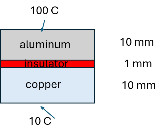
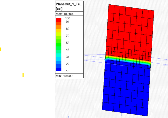
In the first case, the insulation layer is modeled explicitly with a thickness of 1 mm using Option 1 from the table. The resulting temperature profile is shown on the center plane in Figure 2.
As expected, the temperature remains nearly uniform within the high-conductivity solids, while the insulation layer exhibits a strong temperature gradient through its thickness.
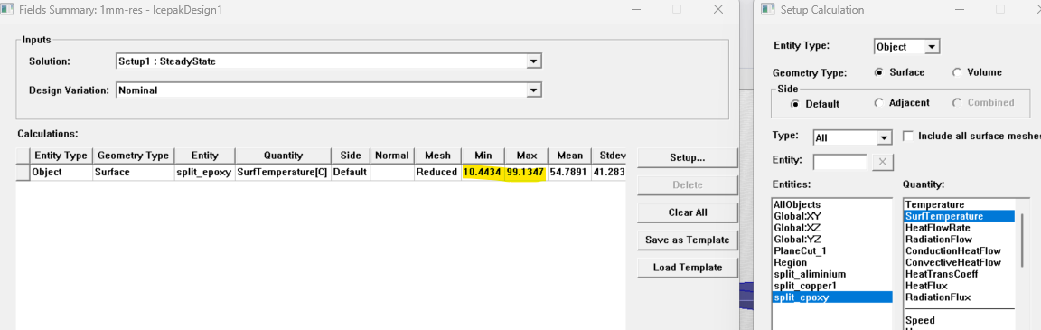
The Field Summary function can be used to calculate the temperature drop across the insulator. By evaluating “SurfTemperature” on the solid surfaces, the temperature drop is found to be approximately 90°C.
Next, the thin insulation layer is modeled as a Conducting Plate with a thickness of 1 mm using Option 2 from the table. There are two possible ways to define the Conducting Plate:
a. Select a face at the interface on either solid.
b. Use a separate sheet object at the interface.
The resulting temperature profiles are shown on the center plane and on the Conducting Plate for Option A. In this case, the solved temperature field shows no effect from the insulation layer, indicating that the Conducting Plate is effectively ignored.
No software warnings appear, and no data is returned for the Conducting Plate when Temperature or SurfTemperature is requested in Field Summary.
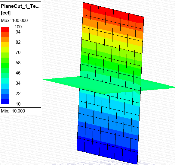
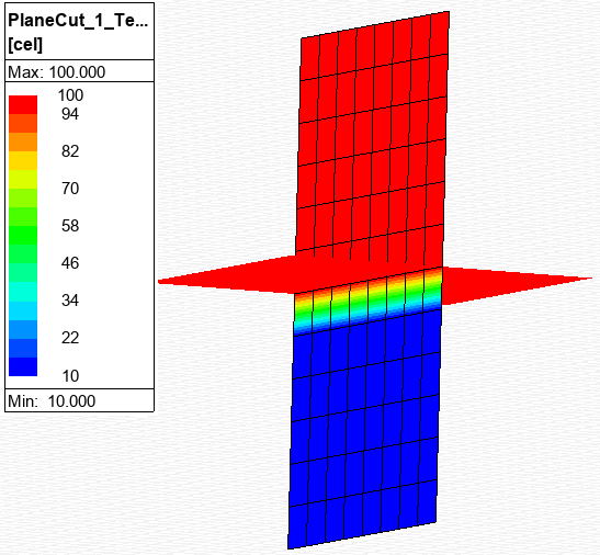
Figure 5 shows the temperature contours on the center plane and on the Conducting Plate for Option B, where a sheet object is used to define the insulator.
In this case, the predicted thermal behavior closely matches Option 1. The effect of the insulation layer appears in the first mesh layer of the lower solid, while the temperature displayed for the Conducting Plate corresponds to the top solid.
This comparison demonstrates why the setup method matters when using Conducting Plates to represent thin solids in Ansys Icepak.
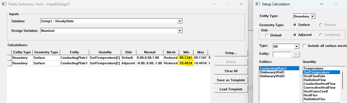
The Field Summary function can again be used to calculate the temperature drop across the insulator. By evaluating SurfTemperature on the ConductingPlate1 object at the Default and Adjacent sides, the temperature drop is found to be approximately 90°C, as shown below.
Overall, this comparison shows that the Conducting Plate approach can reproduce the expected thermal behavior when it is defined using a separate sheet object at the interface.
Defining the plate directly on a solid face, however, does not capture the insulation effect in this example. For this configuration, the sheet-based Conducting Plate approach is therefore the more reliable modeling choice.
Improve Thin-Layer Thermal Modeling in Ansys Icepak
Thin insulation layers, interface materials, PCB features, and metallic surfaces can require different modeling approaches depending on their geometry and thermal behavior. SimuTech Group’s electronics cooling experts can help you select and validate the right Ansys Icepak method for thin solids, conducting plates, and thermal interfaces.

Mert Berkman, PhD Aerospace Engineering
Lead Engineer – Fluids, SimuTech Group
Mert Berkman is an aerospace engineer with a PhD in Aerospace Engineering and extensive experience in computational fluid dynamics, combustion, thermal-fluid analysis, and advanced engineering simulation. At SimuTech Group, he supports customers across complex fluids applications, helping engineering teams model challenging flow behavior, evaluate thermal and combustion performance, and apply simulation more effectively to real-world design decisions. His background spans aerospace research, automotive systems, power generation, turbomachinery, and technical consulting, giving him a broad perspective on how CFD can be used to understand performance, improve reliability, and reduce development risk across highly engineered systems.